|
|
Post by lugnut526 on Sept 26, 2009 18:14:48 GMT -5
my friend picked up a set of MK III that keys about 12 watts, nothing seems to be strapped or monkeyed with. any thoughts will be appreciated.
|
|
|
|
Post by Tombstone (R.I.P.) on Sept 28, 2009 17:47:12 GMT -5
If you don't see any power resistors that have been strapped or jumpered maybe someone has put lower value resistors in it. I'm not sure if using a different final tube would produce that much excessive RF power. That's all I can suggest except if the resistors are the proper value it's time to take voltage readings. Ah, silly thought but have you compared the output reading on different watt meters?
Tombstone
|
|
|
|
Post by Tombstone (R.I.P.) on Sept 28, 2009 17:56:09 GMT -5
Another remote thought. If you're using a power mic maybe the modulation is so high that you're showing that much forward swing on your meter from room noise. If that was the case you would get on the air reports of over modulation. I wouldn't run the thing until you track down the problem. Someone on this forum will probably know more of what to look for.
Tombstone
|
|
|
|
Post by lugnut526 on Sept 29, 2009 2:03:46 GMT -5
found two power resistors that read o ohms ,pulled them and found a very small copper wire across the leads on the back side where they couldnt be seen . working fine now. thanks anyway for the thoughts Tombstone.
|
|
|
|
Post by Tombstone (R.I.P.) on Sept 29, 2009 7:38:58 GMT -5
Glad that you got it straightened out.
Tombstone
|
|
|
|
Post by gator7 on Oct 10, 2009 8:45:55 GMT -5
Another disaster averted. To bad so many people do that to these radios. (strap) the resistors. When I got my 1st MK III it had been strapped.  Good catch Lugnut. ;D 73 |
|
|
|
Post by mark4 on Oct 10, 2009 12:20:39 GMT -5
That is good you found it. I have seen these strapped many times. For some reason thin telephone wire has turned up quite often to strap the dropping resistors. |
|
|
|
Post by Tombstone (R.I.P.) on Oct 12, 2009 18:00:06 GMT -5
Yep, one of my Mark III's had the tell tale toggle switch on the rear of the transmitter. Before even powering it up I pulled the bottom cover off and there it was, the old solid conductor telephone wire connected to a resistor and leading to the switch.
Tombstone
|
|
|
|
Post by don19488 on Jul 8, 2010 7:34:57 GMT -5
Just a tip that you may run into with the MK4s dead key, sometimes instead of actualy strapping across the resistor you will eind that the solid green wire that belongs on the far right hand lug of the 5 lug conection strip has been switched to the far left lug,effectively bypassing the resistor,put it back on the far right lug to have resistor back in circuit.View is looking from back of radio towards the 5 lug conection strip.Hope this is of some help,original info given to me by Fixer,one of the best and yes it did work on my MK4 Regardsdon19488
|
|
|
|
Post by cbrown on Jul 8, 2010 9:51:43 GMT -5
Good tip, thanks!
|
|
|
|
Post by husker on Jun 26, 2019 8:20:06 GMT -5
Sorry for bringing up this old thread, but I just acquired another mrkiii with the same issue. Still learning my way around the Browning side, would it be possible for someone to point me to where I should look for the strapped resistor? Right now I am keying 11.5 watts. The radio has all original Browning tubes EXCEPT for the final and now I see why  thanks in advance |
|
|
|
Post by 2600 on Jun 26, 2019 15:39:23 GMT -5
What you're looking for is R49, normally a 10-Watt wirewound part. This pic shows the area just under the short 2-section "can" filter cap. 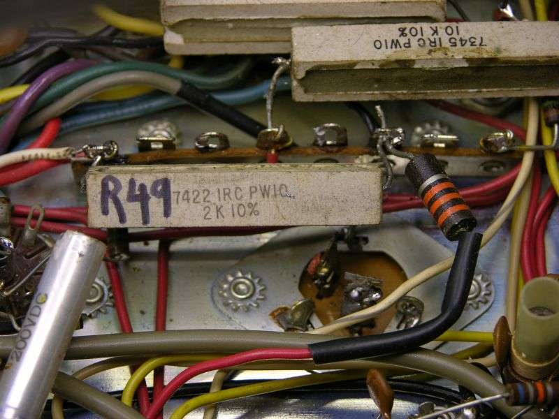 73 |
|
|
|
Post by husker on Jun 26, 2019 16:06:47 GMT -5
So I should look for a jumper if you will right there. Interesting and thank you!
|
|
|
|
Post by husker on Jun 26, 2019 21:43:24 GMT -5
What you're looking for is R49, normally a 10-Watt wirewound part. This pic shows the area just under the short 2-section "can" filter cap. 73 the small one sandbar 1k..this one Chris? Attachment Deleted |
|
|
|
Post by 2600 on Jun 26, 2019 22:02:52 GMT -5
Can't see any markings on the small resistor, but it's clearly in parallel with R49. Odds are its resistance value is a lot lower than 2000 ohms.
It doesn't belong there. Removing it should bring the carrier back down to a safe level.
73
|
|
|
|
Post by husker on Jun 26, 2019 22:17:03 GMT -5
it is a 1k, and it is gone. One problem at a time lol.thanks!
|
|
|
|
Post by husker on Jun 26, 2019 22:22:09 GMT -5
Can't see any markings on the small resistor, but it's clearly in parallel with R49. Odds are its resistance value is a lot lower than 2000 ohms. It doesn't belong there. Removing it should bring the carrier back down to a safe level. 73 any thoughts on why they added a 1uf 50 cap here?  |
|
|
|
Post by husker on Jun 27, 2019 13:44:05 GMT -5
Even with the 1k sandbar removed, I am still getting 8 watts dead key... very strange
|
|
Sandbagger
Administrator/The Boss 
Posts: 6,247 
|
Post by Sandbagger on Jun 27, 2019 15:34:54 GMT -5
Even with the 1k sandbar removed, I am still getting 8 watts dead key... very strange Check the screen grid resistor R23. Should be 15K. |
|
|
|
Post by husker on Jun 27, 2019 15:48:04 GMT -5
Any thoughts on why someone would put a 1uf 50v cap in that spot I circled?
|
|
|
|
Post by husker on Jun 27, 2019 21:59:03 GMT -5
Even with the 1k sandbar removed, I am still getting 8 watts dead key... very strange Check the screen grid resistor R23. Should be 15K. I have a 35k 2 watt in r23 Attachment Deleted |
|
|
|
Post by 2600 on Jun 28, 2019 22:56:24 GMT -5
The 1uf 50V cap is part of the later-version Mark 3 ALC circuit.
The original Mark 3 transmitter from 1970 did not have any sideband modulation limiting. Sometime around 1974 or so the FCC made this a requirement. Browning added it to the Mark 3, but the original version is the only schematic I have found online.
And that one won't have this capacitor. Or the ALC trimpot. Nor the ALC circuit under the chassis to the rear of the SWR Cal control.
73
|
|
|
|
Post by husker on Jun 29, 2019 2:23:03 GMT -5
Interesting, I wonder just how many variants of the MrkIII there are?
Thanks Chris for your help and you as well Dave!
|
|
|
|
Post by husker on Jul 2, 2019 12:17:51 GMT -5
 Any ideas how to change this back to a 3 section from the 4 section it's wired for? |
|
|
|
Post by tubefan on Jul 2, 2019 13:32:57 GMT -5
Exactly like its wired. As far as I can see they only used 3 sections of the can. I see the 4th is empty.
|
|
|
|
Post by 2600 on Jul 2, 2019 14:49:06 GMT -5
Yep. Only three of the four lugs are connected. Should be able to copy the hookup you see.
Just be nice to R60, the 1k 2 Watt resistor. The one in the pic looks like it has incredibly low mileage. We routinely replace it with a 1k 5 Watt wirewound, rather than worry about damaging it from stress removing it from the filter cap.
73
|
|
|
|
Post by husker on Jul 2, 2019 15:18:49 GMT -5
Thanks guys, after I sat for a bit I hit me there are only three sections wired. I also have a wirewound resistor to replace the R60 with. I listen to what that Nomad guy says  |
|
|
|
Post by husker on Jul 3, 2019 23:07:21 GMT -5
And she is alive and kicking! Thanks Chris and Dave!!
|
|