|
|
Post by toolmaker on Sept 3, 2012 23:34:09 GMT -5
Got hold of a nice Astrobeam that is in very good condition. I went over it, and replaced all the fastening hardware, put it together, checked all of the continuity points. Everything seemed fine...until. Hooked to the radio, checked swr, and it was kinda high, I adjusted the stinger, and got it to drop to 1.3-1.5.. didnt seem too bad. Took it up to the roof, and just strapped it to the chimney, swr went up to 2.1, 2.8. Nothing I did would bring it down. put it in the tripod, and it went up a bit more. Mounted it to the rotor, and up it went again !!! Added 5' of mast thinking the hoop was reflecting off the rotor, and now the swr is up to 3.1-3.5.
I added the matching coax on the antenna side, and it went up a bit more. Took the matching coax off, and added it to the radio side, and the swr now sits at 2.3- 2.5. Not sure what to do to get it down. Id like it to sit at 1.5 or better, but that seems to be far off. Any advice is greatly appreciated. Im using 46' of lmr-400 coax, that worked fine when I had the Imaxx up, and never had a problem.
|
|
|
|
Post by homerbb on Sept 4, 2012 3:39:57 GMT -5
In my experience with the Astroplane the antenna requires a minimum of 12' of mast below the ring per the owners manual . The coax should be zip tied, or taped along one side of the mast all the way down to at least the 9' point below the ring where you should have a coax choke in the feedline.
coax choke will be 5 to 6 wraps of the coax around a 4.25 inch non-conductive former if it is small diameter coax like RG58 or 213.
If it is larger diameter coax you should use 5 to 6 wraps around a 6" non-conductive former.
|
|
Sandbagger
Administrator/The Boss 
Posts: 6,250 
|
Post by Sandbagger on Sept 4, 2012 6:54:27 GMT -5
Got hold of a nice Astrobeam that is in very good condition. I went over it, and replaced all the fastening hardware, put it together, checked all of the continuity points. Everything seemed fine...until. Hooked to the radio, checked swr, and it was kinda high, I adjusted the stinger, and got it to drop to 1.3-1.5.. didnt seem too bad. Took it up to the roof, and just strapped it to the chimney, swr went up to 2.1, 2.8. Nothing I did would bring it down. put it in the tripod, and it went up a bit more. Mounted it to the rotor, and up it went again !!! Added 5' of mast thinking the hoop was reflecting off the rotor, and now the swr is up to 3.1-3.5. I added the matching coax on the antenna side, and it went up a bit more. Took the matching coax off, and added it to the radio side, and the swr now sits at 2.3- 2.5. Not sure what to do to get it down. Id like it to sit at 1.5 or better, but that seems to be far off. Any advice is greatly appreciated. Im using 46' of lmr-400 coax, that worked fine when I had the Imaxx up, and never had a problem. I had an Astro Beam back in the 80's. I never had a problem with SWR. I had the antenna mounted on 10' of mast which put the rotor right at the ring level. The whole thing was mounted on a 40' tower. But the important thing with the AB is that you absolutely need to use the 6' matching coax stub that comes with the antenna. Without it, the SWR is over 3:1. |
|
|
|
Post by toolmaker on Sept 4, 2012 8:29:49 GMT -5
Thanks for the replies. Homer, I did try to do the coax choke, but Im short on the feedline. I could use a coupler I guess, and make the wrap, but I dont really like using them. I didnt think the choke would do anything to help the antenna resonance, I know it may help with some of the feedback issues I sometimes have, and maybe with the new tvi madness. The antenna seems to be physically too long, but it measures out correctly per the set-up sheet. I say too long because the higher I go with mast, the higher the swr goes. The best match Ive had was when the antenna was on the ground, and the mast jammed into the earth, with the hoop section about 18" from the ground. I hate to say it, but I may have to put a tuner in line.
|
|
|
|
Post by "Doc"Hammer on Sept 4, 2012 9:40:51 GMT -5
Sounds like you are getting reflection off surrounding objects..Make sure your mast is earth grounded well, also You mentioned having replaced hardware...I have seen folks use an aluminum spreader when re-building an astrobeam or astroplane..that spreader must be made of fiberglass or some other non-conductive material(see image for the part I'm referring to). I ran one of these beams for several years and it always worked great.. Attachments:
|
|
|
|
Post by toolmaker on Sept 4, 2012 10:18:04 GMT -5
Thanks Hammer, the mast is grounded to my service ground rod, and there are no objects withing 18' of the antenna. I know the antenna will work great once I get it all buttoned up, but getting there is proving to be a major pain in the butt. The spreader is a fiberglass dowel.
|
|
|
|
Post by homerbb on Sept 4, 2012 11:57:00 GMT -5
if you must go down with the stinger then do so. If the one yhou have won't go ow enough, then get a wooden dowel and use it. Simply cover the dowel with aluminum duct tape and remove it a little at a time until you are where it needs to be. This will tell you where the stinger length needs to be.
|
|
|
|
Post by toolmaker on Sept 4, 2012 22:18:23 GMT -5
I will be shortening the driven element over the next couple of days. That section is two pieces, and can be shortened by loosening the clamp. I am more convinced that the mast is considered to be part of the antenna. Doing the math, there isnt enough length between the driven element, and the hoop section to equal a half wavelength. If you include the recomended 10' mast, the antenna would become long. I also removed the ground from the mast to see what would happen, and the swr dropped a full point. This is of course no way to leave an antenna, but it leads me to believe more and more that the mast is part of the antenna, or I have some massive common mode reflect getting in there. I also dont like the way the feedpoint is set up on the antenna. Without a 90* adapter the coax is forced to bend at an angle that I suppose could cause a problem at the connector. Ill try a 90* adapter, and shorten the driven element, and hope for the best. Worst case is Ill have to put a tuner in line.
|
|
|
|
Post by homerbb on Sept 5, 2012 10:40:48 GMT -5
With the Astroplane the mas plays a significant roll. I would assume it is the same with the Astrobeam..\
|
|
Sandbagger
Administrator/The Boss
Posts: 6,250
|
Post by Sandbagger on Sept 5, 2012 13:11:16 GMT -5
With the Astroplane the mas plays a significant roll. I would assume it is the same with the Astrobeam..\ Interesting though, the Astro Plane does not require the 6' coax stub, while the Astro Beam does. Evidently the presence of the parasitic elements on the beam has an impedence changing effect. |
|
|
|
Post by toolmaker on Sept 5, 2012 14:25:14 GMT -5
I have a feeling that coax match is needed because the antenna is electrically too long when a 10' mast is in use. as near as I can tell, if the mast is considered part of the antenna, then the longest mast that could be used would be 55". The antenna has a 77 5/8" driven element, and 84" of radial extending to the hoop. Since both ends of the hoop radials are contiguous, the two hoop radial are electrically one 161" element. Now add 10" of mast, and its way over 1/2 wave. Interestingly enough, those values put the antenna very close to a 5/8 wave if the mast is considered to be part of the antenna. So with the recommended 10' mast the antenna measures very close to a 5/8 wave, and without it in consideration, the antenna is far too short for even a half wave.
Now it gets a bit goofy, because the reflector is 222 1/4" long, the director is 198 1/4" long. If its a 5/8 wave driven element the reflector should be 295" long, and the director 266" long using the +/- 5% formula. Normally I dont do math, but I cant get this thing to tune in, and is making me crazy.
|
|
|
|
Post by homerbb on Sept 5, 2012 17:02:25 GMT -5
Interesting though, the Astro Plane does not require the 6' coax stub, while the Astro Beam does. Evidently the presence of the parasitic elements on the beam has an impedence changing effect. Yep, I would assume so in the same manner that a dipole can be fine without a matching system until you put it inline with some parasitic to form a Yagi/ |
|
Sandbagger
Administrator/The Boss
Posts: 6,250
|
Post by Sandbagger on Sept 5, 2012 17:13:33 GMT -5
I have a feeling that coax match is needed because the antenna is electrically too long when a 10' mast is in use. as near as I can tell, if the mast is considered part of the antenna, then the longest mast that could be used would be 55". The antenna has a 77 5/8" driven element, and 84" of radial extending to the hoop. Since both ends of the hoop radials are contiguous, the two hoop radial are electrically one 161" element. Now add 10" of mast, and its way over 1/2 wave. Interestingly enough, those values put the antenna very close to a 5/8 wave if the mast is considered to be part of the antenna. So with the recommended 10' mast the antenna measures very close to a 5/8 wave, and without it in consideration, the antenna is far too short for even a half wave. Now it gets a bit goofy, because the reflector is 222 1/4" long, the director is 198 1/4" long. If its a 5/8 wave driven element the reflector should be 295" long, and the director 266" long using the +/- 5% formula. Normally I dont do math, but I cant get this thing to tune in, and is making me crazy. Doing math will only make you crazier, especially if you don't understand all the variables at work. The way I see it, if the mast was a critical part of the equation, then it would be sensitive to the length of the mast. In other words, someone mounting the antenna on a 20' mast would get a different SWR (and likely different radiation patterns as well), than someone who mounted it on a 40' tower. Just a fleeting thought, when you put together the Astro Plane radiator section, the beam differs from the omni in how the top section is mounted. It wasn't 100% clear in the instructions, and when I had mine I almost mounted it the way the omni was constructed instead of sliding the top section over the little stud that you affix to the top of the boom mounting plate. Make sure you didn't make the mistake that I almost made 30 years ago...... |
|
|
|
Post by homerbb on Sept 5, 2012 17:28:23 GMT -5
I would imagine that you have made sure of the insulators. Be sure they are all as they should be. The reflector and the director are to be isolated from the boom, and the driven isolated as well. I would check the tuning stub for no grounds center to braid, and continuity from end-to-end on both the stub conductors. If you have any doubts about the stub's health, make another one. Where the coax connects to the antenna the center conductor must be isolated from the top cross/jumper bracket contained within the boom to driven mount insulator with contact to the short side of the of the driven skirt/radial only. The braid must have direct ground to the the long side of the antenna. It is okay to try and figure out what that Astroplane inserted into the beam is if you want (I think it is a 1/2λ), but so not attempt to tune it based upon your thoughts about it. Do as the manual says and tune slightly with the upper whip. The distance between the two halves of the lower section (skirt/radials) must be exactly the distance apart prescribed in the manual. It is critical. As for your speculations regarding the nature of the AP that comprises the driven element, bear in mind that the skirt is part of the antenna as well as plays a functional roll in its match and radiation pattern. Regardless of its nature, it is imperative that you have the antenna built to specs, and go from there. 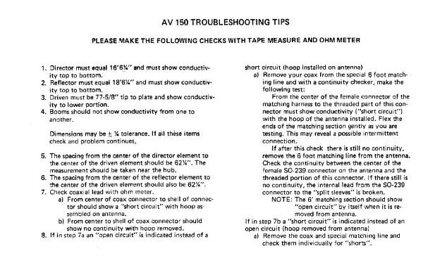 |
|
|
|
Post by toolmaker on Sept 5, 2012 18:37:35 GMT -5
Disaster raised its mighty head during the nite. 80 mph winds came through and bent it over like a piece of wire. Didnt see it until I got home from work. The whole shootin match came down. Busted the insulators, and bent the mast at the rotor. My AstroBeam is now an AstroPlane. I took the director, and reflector off, mounted it to a new mast, stuck it in the tripod, checked the swr, and what do ya know... flat swr. Well 1.2 anyway. One of the insulators survived, so Ill take it to work, and make new ones out of some glass reinforced nylon block, or another suitable material. If it werent for bad luck, Id have no luck at all...HEE HAW.
I really appreciate all of the replies, and great advice folks.
|
|
|
|
Post by homerbb on Sept 5, 2012 18:51:24 GMT -5
What a deal . . .
If you run out of that insulator material try some of the maintenance free decking material. It is decent. I plan on using it to make the insulators for my next Astroplane.
|
|
|
|
Post by toolmaker on Sept 6, 2012 15:54:56 GMT -5
Its too bad the driven element doesnt have the thread in the end of it. Id be able to use some stainless welding wire for the top hat radials.
|
|
|
|
Post by homerbb on Sept 7, 2012 16:29:47 GMT -5
Its too bad the driven element doesnt have the thread in the end of it. Id be able to use some stainless welding wire for the top hat radials. You can do it. Substitute the upper vertical with a tube 45-3/4" and use a set up like this to top it off: 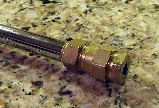 |
|
|
|
Post by toolmaker on Sept 7, 2012 19:22:41 GMT -5
Looks like a brass compression fitting. Ill press one in the end of the tube, and cross drill it. I have too much time on my hands at the shop anyway. So far it seems to work ok without it. The folks I talk to normally have said my signal has dropped 2s units from when the Astro Plane, was an Astro Beam
|
|
|
|
Post by zman on Sept 11, 2012 18:54:26 GMT -5
Forget the Astrobeam as it is a joke to try to get a decent match on. Id just use it as an astroplane and get a standard 3 element beam... I have had 4 astrobeams and not ONE of them i could ever get the match down on.........  |
|
Sandbagger
Administrator/The Boss
Posts: 6,250
|
Post by Sandbagger on Sept 12, 2012 6:44:58 GMT -5
Forget the Astrobeam as it is a joke to try to get a decent match on. Id just use it as an astroplane and get a standard 3 element beam... I have had 4 astrobeams and not ONE of them i could ever get the match down on......... Were you using the matching coax stub? I had an Astro Beam, and a few other locals also had them and none of us had a problem with the SWR. Now it's true that the antenna favored the lower end of the band (channel 1) and the match climbed higher, the further up you went, but my SWR was always under 1.6:1. |
|
|
|
Post by zman on Sept 12, 2012 12:32:50 GMT -5
I used the stub and it made NO DIFFERENCE!! This week i'm getting another one from a lady so i guess i'm a glutton for punishment..... ;D  |
|
|
|
Post by homerbb on Sept 12, 2012 21:21:23 GMT -5
Were you using the matching coax stub? I had an Astro Beam, and a few other locals also had them and none of us had a problem with the SWR. Now it's true that the antenna favored the lower end of the band (channel 1) and the match climbed higher, the further up you went, but my SWR was always under 1.6:1. For that matter, although I've had excellent experiences with both my original AP and my homebrewed one, when this antenna is put on an analyzer, and when it is modeled, the AP is resonant below ch 1. The SWR bandwidth is broad enough to provide a very good match across the CB 40 and beyond. I have little doubt the experience will be similar with the AB. |
|
|
|
Post by zman on Sept 13, 2012 20:23:55 GMT -5
Im going to eat my words here  as the AB i just got today after a good tune, is well below a 1.5=1 across all 40. It took adjusting the stinger quite a bit to get it to tune inside the regular 40 channels but it DID tune! ;D |
|
|
|
Post by homerbb on Sept 13, 2012 21:37:48 GMT -5
Sweet!
Which end is the slight bit lower, 40 or 1?
|
|
|
|
Post by toolmaker on Sept 15, 2012 9:10:20 GMT -5
I know mine tuned lower on 1 when it was a beam, but now that its a plane its very close to 1.3 across 1-40. My parts are almost done so pretty soon Ill be turning it into a beam again. Gonna try leaving the stinger where its at and see how it is. I took some empty edm wire spools, and bored the hole out to 1 1/2" split it across the length on the band saw,and used a nylon worm clamp to hold it tight against the mast for my coax choke. Drilled opposing holes on the faces to feed the coax through at the ends of the wind. Works like a million bucks. The spool diameter is right at 4".
|
|
|
|
Post by homerbb on Sept 15, 2012 10:50:49 GMT -5
Well I approve. It sounds like something I would do.
|
|
|
|
Post by zman on Sept 17, 2012 18:33:05 GMT -5
It still has a 1.2=1 across all 40 and seems to be holding it. It seems to favor the low end of the band as someone else mentioned.. Im impressed! ;D
|
|
|
|
Post by homerbb on Sept 17, 2012 18:52:28 GMT -5
Let us know how it works out on the air.
|
|
|
|
Post by zman on Sept 19, 2012 22:19:21 GMT -5
so far so good. still decent swrs.
|
|


 as the AB i just got today after a good tune, is well below a 1.5=1 across all 40. It took adjusting the stinger quite a bit to get it to tune inside the regular 40 channels but it DID tune! ;D