|
|
Post by wally on Oct 31, 2017 22:00:21 GMT -5
Hello everyone, I recently found a nice Mark III to play with. I found that it has a fairly loud hum while transmitting, which I then tried to eliminate the simple things (mic, grounding issues, etc.). I believe that this is going to be a full capacitor replacement, did some voltage checks the other night with my SAM manual, and all of them were off on the transmitter, have yet to test the receiver. In the case of replacing the capacitors this is not a big deal, but the filter capacitors have me thinking about how to replace them without breaking the bank. I have been reading on several ways to replace them, was wondering which methods people are using to do this, if you go all out & buy the multi-cap capacitors in original form, or do any of you replace them with modern components. I can do either way, the cost is the only issue at the moment. Thanks
|
|
|
|
Post by bill on Oct 31, 2017 23:09:16 GMT -5
Here are a couple of Articles that should help while you await for more responses... You could also use this Website's Search Feature and read previous related Discussions too... antiqueradio.org/recap.htm www.nmr.mgh.harvard.edu/~reese/electrolytics/I realize a lack of funds may prevent one from performing what they hoped, but practically any NEW Capacitor, NOT New Old Stock, will be better than 40 plus year old Capacitors... Avoid buying New Old Stock, as they are just that, OLD... You're measuring Voltage differences and should also make note that Carbon Composition Resistors also do not age well and it is common to find they are out of Tolerance... For Multi-Section Electrolytic Caps, I sourced mine for my Tram D201A from a Vendor that caters to Musicians for their Amplifiers, they were JJ Brand and mounting them required the use of a Clamp that was sold separately which needed to be Bolted to the Chassis Deck... www.jj-electronic.com/en/capacitors You would have to compare Prices of other Manufacturers' offerings too... It appears the Factory used Twist-Lock Caps are once again made using Mallory's original Tooling and Specifications www.cedist.com/products/capacitors?filters=Type%3DMulti-Section%20/%20Can%20Type |
|
|
|
Post by wally on Nov 1, 2017 15:23:57 GMT -5
Thank you for your response Bill, Ive been searching for suppliers of the original style twist lock cap, I found the CE caps last night after cross reference of the original filter cap number. What I was mostly wondering is if anyone has used modern smaller caps, and either used the original can to mount them in, or mounted them on the bottom side of the radio. It looks like this could get expensive in a hurry with the twist lock caps, but if that is the way to go Ill do it that way. I want this radio to last, so I will avoid cheap caps, but using quality smaller caps would be fine, just need an opinion on the safety factor of doing it that way. Thanks again
|
|
|
|
Post by 2600 on Nov 1, 2017 17:07:25 GMT -5
(page 252, post 3772) This is an experiment. I lost the original file and pics uesd for this procedure. Hard drive crash 5 or 6 years ago. But the images were posted at ImageShack. This post was on the CB Tricks forum, now crashed. --BUT__ I found the old post, through the remaining back door there. Copied this text from it and manually inserted the image links. Might be a bit scrambled, but I'll fix it if I can once it's posted. Sure, this info should get composed as a web page and posted on my site. Soon. At least that's what I said in May 2009 when this was originally posted at CB Tricks forum. But for now, this makes the info accessible while I get it refined. Sooner or later I may try to sell "parts kits" to perform this upgrade. But for now, this is just an experiment. No reason you can't shop around for the parts yourself. There is nothing wrong with your television. Do not attempt to adjust the picture. Mark III SSB transmitter: We'll tackle the small stuff first. These are the small capacitors and resistors that are cheap and can damage a tube when they go bad. 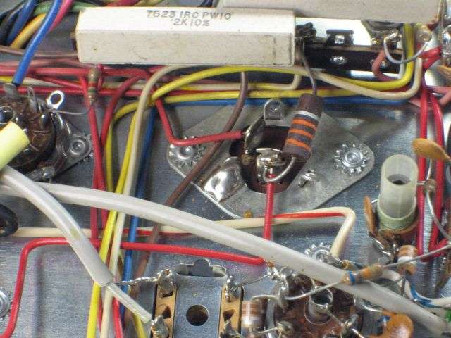 C47 is the skinny short aluminum twist-lock can near the final tube. It has two sections. No need to remove C47. Clip the 33k 1W. Resistor and red wire from the lug where they're soldered. The red wire should get stripped, tinned and lap-soldered to the free end of the 33k resistor. Sleeve the splice. 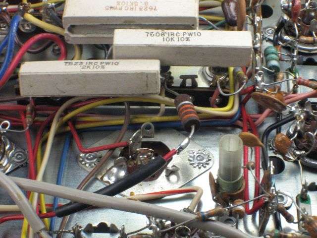 Follow THIS red wire to pin 1 of V8, the 12AU7A tube. Solder the negative lead of a 10uf 450V radial cap to the ground lug nearest pin 1, and the positive lead to V9 pin 1. 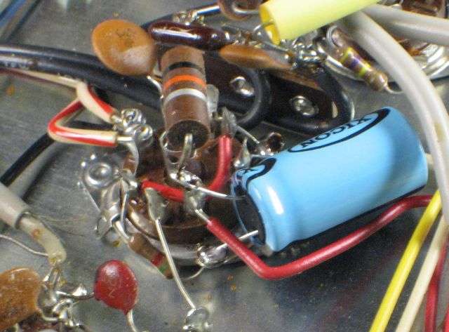 The other lug on C47 has a single red wire on it. Clip it from C47 and follow this wire to a tie strip near the main filter capacitors. Remove the red wire from this lug, and put a 10uf 450V radial to this lug and the ground lug next to it. Pull the red wire out of the harness. 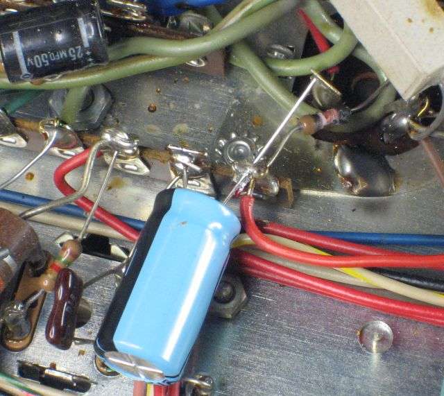 Remove the parts from pin 3 of V9, the 6BQ5. All 3 of them. 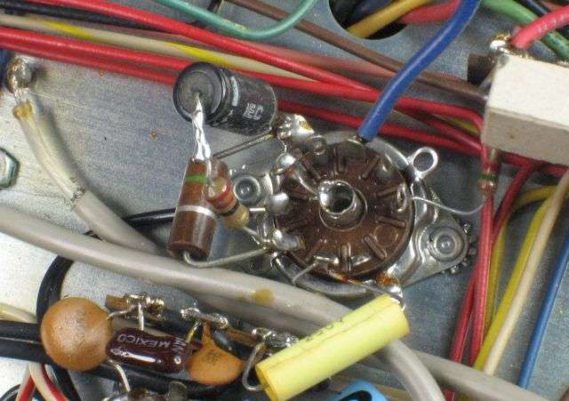 Install a 150-ohm 2W wirewound resistor from pin 3 to ground. Add a 22uf 50V radial cap with the negative lead to the ground lug, and the positive lead to V9 pin 3 so that it's wired in parallel with the resistor. 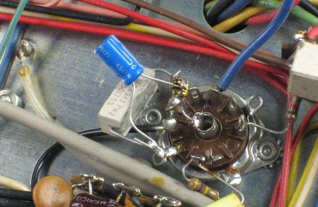 There is a 1.5k 1/2W resistor on pin 9 of V9. If it looks okay, leave it alone. If it looks damaged, replace it with the 1.5k 1W resistor supplied. And if it ain't broke, don't fix it. Under the power transformer is a rectifier bridge (4 lead wires) fed by the blue wires from the power transformer. The two 25 uf axial caps get replaced each with a 22uf 50V radial cap. The old caps have the positive end marked “+”. The new ones have one end marked “-”. The longer of the two leads is the positive one, also. 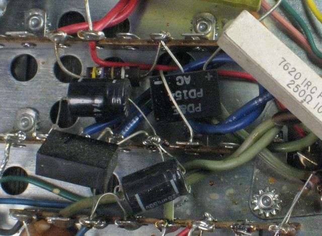 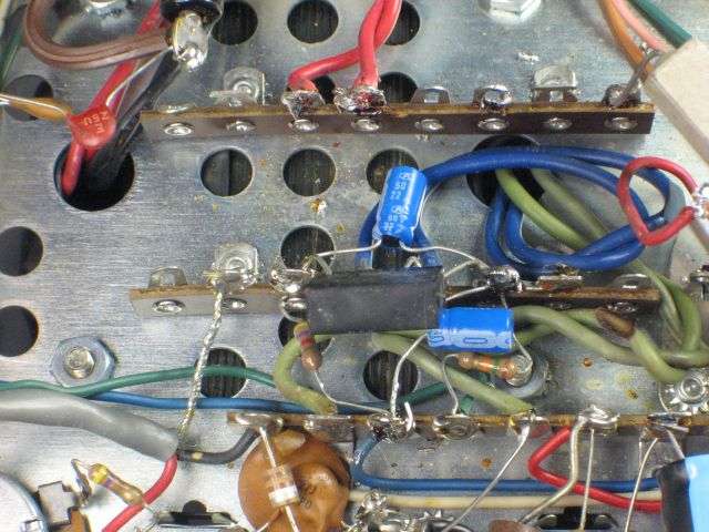 If you look at the power transformer in the schematic diagram, find the middle one of the three secondary windings. This is the B+ winding. We'll remove all the parts between that winding and C61C EXCEPT R59. Leave R59 (250 ohm 10W) attached to the right-hand lug of the tie strip. Start with the square 3-legged rectifier, C62 and R64, the 4.7 ohm 1-Watt resistor. If you look at C62 and C61C in the schematic, you'll see that they are in series. One section of C61 has only a single red wire that leads back to a lug where the negative end of C62 joins one red wire from the power transformer. Remove C62 and replace it with the new 47 uf 250 Volt axial cap. The 47uf 250 Volt radial cap gets its positive lead on this lug too. This part now takes the place of “C61A”. The negative end of this radial cap goes to a ground lug on the tie strip. The 5.6-ohm 2W wirewound resistor replaces C64. Two 1N5408 rectifiers now replace the single 3-legged block. 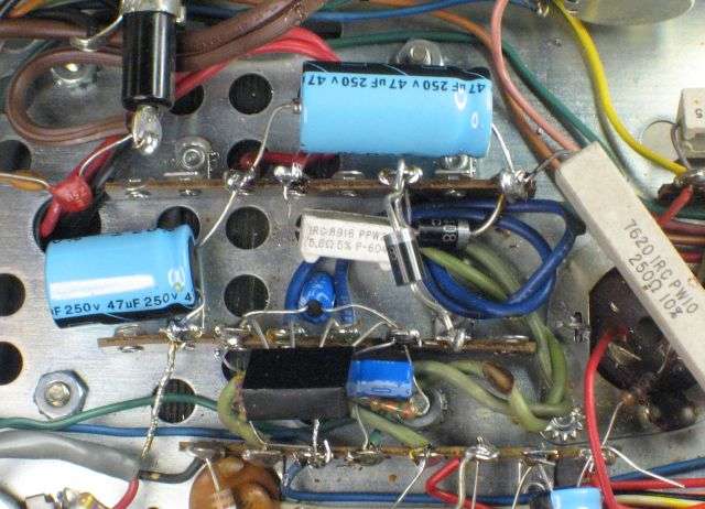 Please note that the hookup to the two red transformer wires has been reversed. Originally, the red wire on the left fed the 4.7-ohm 1W resistor R64. The NEW (5.6-ohm) R64 is now attached to the RIGHT-HAND red transformer wire. And the two capacitors C62 and C61A are now fed from the LEFT-Hand red wire, and not the right-hand red wire the way the factory did it. This change to the layout just makes life easier. Now it's time to replace the 3-section twist-lock filter C61. One lug has a now-disconnected red wire on it. Ignore this lug. Take a reasonably-large pair of diagonal cutters and clip each of the other two positive lugs below the wire connections. This will leave the two lugs and the wires/resistors soldered to them hanging from the lead wires. Makes it easier to keep straight where they will go on the new C61. 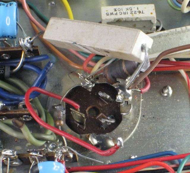 I won't repeat the picture of needle-nose pliers twisting the twist-lock tabs on the old C61 until they break off. And I won't show you a drill bit that's removing the rivets from beneath the metal ring. They have to go. There is a pic in the RECEIVER procedure posted elsewhere in this section. 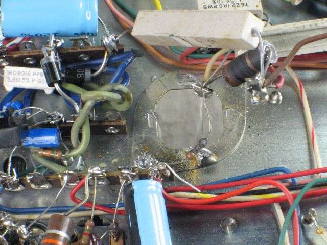 Here's where the new C61 goes, as seen from above. It's best to have the head of the tension screw on the clamp facing the rear of the radio. Makes it easier to get a screwdriver onto it so you can tighten the clamp AFTER it's turned around the right way. You want the negative lug on the new filter to be alongside the ground lug under the nut closest to the front of the radio. 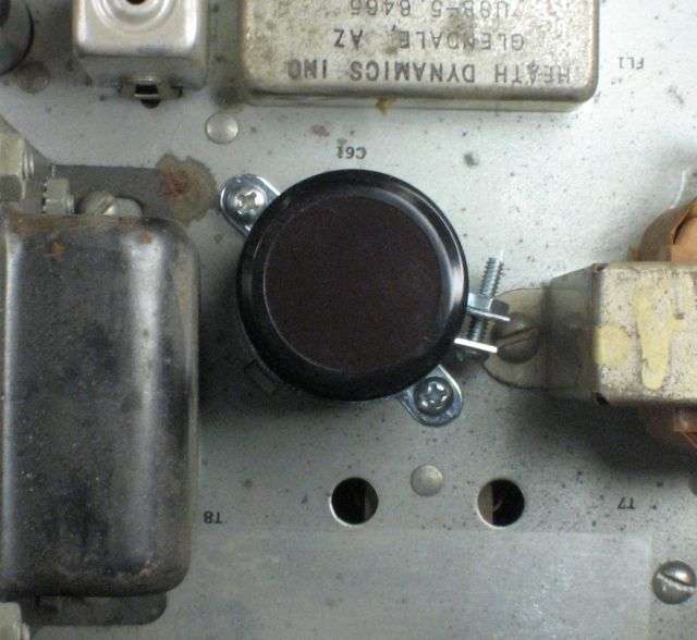 Install the new R60, 1k 5-Watt wirewound across the two positive terminals of the new C61. Remove the old R51, the 3.3k 1/2Watt that was burned in the prior pic from the inboard-end lug of the tie strip. Insert one lead of the NEW R51, 3.3k 1-Watt into the inboard-end lug and solder that end. Line up the ground lug under the front-most screw holding the C61 clamp and solder it to the negative lug of the new C61. May help to pass a short bare wire through the hole on each of these two lugs before soldering them together. 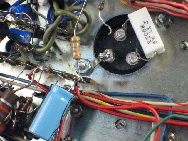 Now we're going to transfer the stuff that's still attached to the two cut-off lugs of the old C61. It's best to unsolder them from the old lug. Go ahead and clip THE OLD LUG, but try to preserve the length of the old leads. You may need it. One lug has four lead wires in it: 1) one end of R62, the 22k 10Watt wirewound that leads off to the relay coil. 2) one end of the old R60, the burned 2-Watt, 3) a white wire, and 4) one end of the old R51, the burned (usually) 3.3k 1/2 Watt resistor. Move the white wire and the free end of R62 to the rear-most lug of the new C61. Insert the free end of the NEW R51, 3.3k resistor. This makes four, total. Now would be a good time to solder this lug of the new C61. 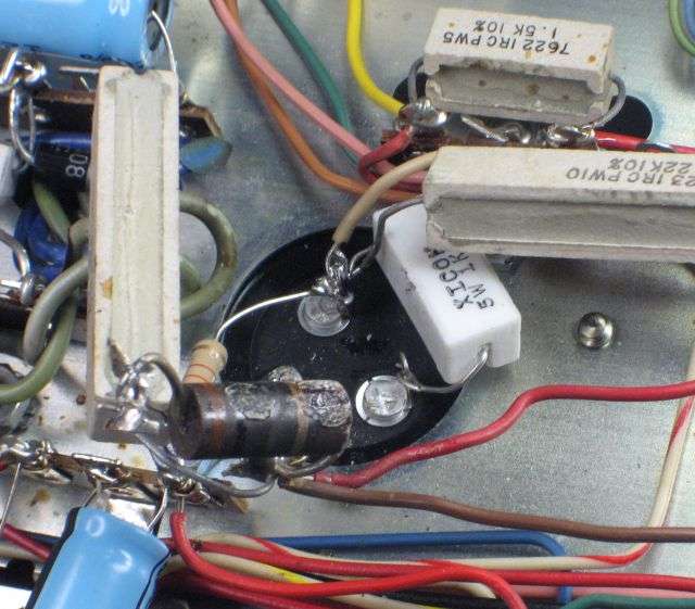 Now remove the wires from the remaining severed lug from the old C61. Poke the now-free end of R59, the 250-ohm 10-Watt wirewound, the brown wire and the red wire into the front-most lug of the new C61. Should be a total of four, counting one end of R60, the 1k 5Watt. 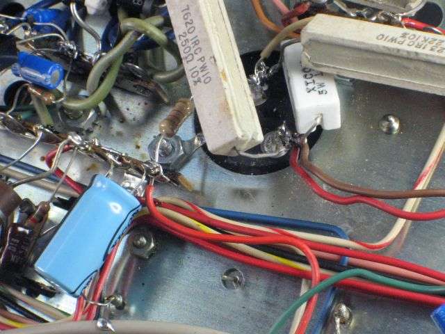 This completes the procedure. The radio should now be ready to power up s-l-o-w-l-y with your variable-AC power supply the first time. Just be sure that the fuse is NO BIGGER than 2 Amp. And if you don't have that variable AC transformer supply, you'll just have to plug it in with fingers crossed. Or, you could go back over the procedure and check your work for accuracy. First. As the old carpenter said, "measure once, cut twice". And if the radio DOES immediately smoke your nice, shiny new R51 (3.3k) this means that your mode selector is shot. The brown bakelite wafer insulation has broken down and turned to carbon. R51 is a typical first (but NOT 'only') casualty. If your original R51 looked clean and shiny, I recommend replacing it with the new one anyway. The original R51 is a carbon-composition resistor and easily damaged by unsoldering stresses. Safer to just install the new one, even if the original R51 looked fresh as a daisy. 73 |
|
|
|
Post by wally on Nov 1, 2017 20:43:47 GMT -5
Thank you 2600 for the info! I miss being able to visit the CBTricks site, was a very useful source for info until it crashed. I will need to get some parts ordered up, and once they get here I can get started on this. I slowly ventured into tube radios as of late, so this is a bit new to me, but also a bit simpler to work with than de-soldering parts from a circuit board. I will keep this post updated, just have to get parts first. Thanks again
|
|
|
|
Post by wally on Nov 11, 2017 1:38:22 GMT -5
I did a little bit more with this tonight, have not ordered anything yet. After talking to the guy I got this radio from, he said that he never had this issue with it, and he ran it alot. So after hearing that, I decided to start checking for any other sources for the hum. If I turn the mic gain all the way down, the hum goes away. If I remove V8, the 12AU7 tube, the hum goes away, with no audio as well. What could this have to do with this issue? I dont have any 12AU7 tubes around, so I tried a 12AX7 in its place, still have hum. When I spot the transmitter & receiver I also have the hum. Im thinking the issue could be a bad ground somewhere around the 12AU7, the mic gain pot could be dirty, or the tube could be bad, but doubtful on that one. Any ideas?
|
|
Sandbagger
Administrator/The Boss 
Posts: 6,247 
|
Post by Sandbagger on Nov 11, 2017 9:32:16 GMT -5
I did a little bit more with this tonight, have not ordered anything yet. After talking to the guy I got this radio from, he said that he never had this issue with it, and he ran it alot. So after hearing that, I decided to start checking for any other sources for the hum. If I turn the mic gain all the way down, the hum goes away. If I remove V8, the 12AU7 tube, the hum goes away, with no audio as well. What could this have to do with this issue? I dont have any 12AU7 tubes around, so I tried a 12AX7 in its place, still have hum. When I spot the transmitter & receiver I also have the hum. Im thinking the issue could be a bad ground somewhere around the 12AU7, the mic gain pot could be dirty, or the tube could be bad, but doubtful on that one. Any ideas? Can you set your bias? Reason I'm asking is I also had a hum when I hit the spot button, and it turned out that the filter caps for the -40V bias supply (C59, C60) were bad. I was unable to set the bias, and replacing those caps fixed the problem, and also took away the hum when the spot was activated. Beyond that, it would be helpful to determine if the hum is 60Hz or 120hz. A 120hz hum indicates (usually) that filter caps are going bad. While a 60 hz hum indicates ingress into the audio circuits from a 60 Hz line frequency source. Sometimes, this could be due to a bad ground (Even in the mic itself), or a ground loop, or a tube with a heater to cathode short. The fact that turning the mic gain down eliminates the hum, shows that the hum is being introduced at a very early mic amp stage. So I would focus my attention in that area. |
|
|
|
Post by SIX-SHOOTER on Nov 11, 2017 11:57:38 GMT -5
Thank you 2600 for the info! I miss being able to visit the CBTricks site, was a very useful source for info until it crashed. I will need to get some parts ordered up, and once they get here I can get started on this. I slowly ventured into tube radios as of late, so this is a bit new to me, but also a bit simpler to work with than de-soldering parts from a circuit board. I will keep this post updated, just have to get parts first. Thanks again Must been a short crash because I have used it several times this week & it worked fine & is NOW as well? SIX-SHOOTER |
|
|
|
Post by wally on Nov 11, 2017 13:01:58 GMT -5
I can set the bias, no problems with that setting, the radio has good output (seems kinda high, 6 watt deadkey - will address that later). It has a definite 60hz hum, I can still hear it without the mic & jumpering ground & transmit pins. Im going to see if I can trace this down more later today, I think I might be looking in the right area.
|
|
|
|
Post by wally on Nov 11, 2017 13:08:24 GMT -5
Every time I try to log in over there I can log on, but if I click on any posts or pages I get an error screen. Been like this for months now, kinda bummed about it since I used to visit there quite often, been there since 2009. Maybe someone could help me out with that one.
|
|
|
|
Post by 2600 on Nov 12, 2017 17:00:59 GMT -5
The CB Tricks Forum software had a crash around March 1. Bennie told me he was trying to fix some other problem. Didn't say which one.
The result is that the indexing of the message database became corrupted. The index info that organizes the stored posts by forum section no longer works.
What does work is the index that organizes messages by username. You can click on a user name at the bottom of the forum's main page, or use the "search for users". When you're on a user's info page, there is a link at the left side of the screen that says "show posts". This is how new posts are being made, through this "back door".
But any attempt to access the individual sections of the forum results in an error.
Bennie has dropped off the radar. Haven't talked to him since the middle of March. At least one member dropped by his house and found nobody home. He left a note, but no word on any response to it.
I don't have any of the admin-level access necessary to do anything about this level of fault. Don't really have the skills, so I'm better off not having access to things I might break, as I see it.
A mystery that only grows deeper by the month.
73
|
|
|
|
Post by wally on Nov 12, 2017 22:08:54 GMT -5
That is too bad, I miss that forum.
|
|
|
|
Post by wally on Nov 25, 2017 1:30:29 GMT -5
Hey guys, Im now in the process of ordering parts. While I have been checking & double checking component values, in the receiver I found some things that were changed from what my SAMS book says it should be. The main filter cap, C45, 40uf/450v has another 3 section 40uf/450v cap glued to the top of the chassis (tube side) wired parallel to C45. I have no idea what was trying to be done with this, as well as C45 had been replaced at some point in time with a 3 section cap, 40/40/50uf 450v. Any ideas on what is going on here? Also I found that C66, which is supposed to be a 20uf/450v cap has been changed to a 40uf/450v cap. Any ideas on that? Im going to get the parts here soon, so if these mods are more of a hack they are going, Ill put it back to the way the schematic states. Thanks again
|
|
|
|
Post by 2600 on Nov 26, 2017 15:54:55 GMT -5
The second 3-section capacitor wired in parallel with the one mounted to the chassis would probably be a sloppy fix for failed sections in the one mounted to the chassis. If one or more sections of C45 became an open circuit, connecting the new one in parallel will stop the hum.
Even if C45 was replaced once in the last 45 to 47 years the replacement could easily be old enough to have gone bad by now.
It's generally a bad idea to leave a failed electrolytic cap in the radio, even if putting a good one in parallel appears to fix the problem. The failed cap can still draw leakage current, get hot and blow up. Removing it from the circuit before connecting a good capacitor is the accepted method of repair.
C66 is the "ping" capacitor. The higher the capacitance value, the longer the ping. We also replace the resistor that feeds into C66. R56 is a 2.2k (red-red-red) half-Watt resistor. We replace it with a 2-Watt part. A larger value for C66 lengthens the ping, but can overheat R56. Making it a "replace anyway" part is cheap insurance. If someone decides he wants a longer ping after we have done the repairs and puts in a larger cap, the original resistor could fail from the stress, even if it checks good today.
There is a myth out there that a longer "ping" can stress the relay in the transmitter, and reduce its service life. Not true. R56 limits the relay's current feeding into C66 to a safe level, no matter how large a capacitor you use. But the actual stress risk is to R56, not the relay. Never have seen a 2-Watt resistor used at R56 overheat in a Mark 3 receiver. The original half-Watt part has that risk.
73
|
|
|
|
Post by wally on Nov 29, 2017 21:59:12 GMT -5
Thanks Nomad, I have parts coming in, supposed to be here Thursday & Friday, so I should be able to get started on it Friday. I think Ill do the receiver first, I ordered new wirewound resistors as well. I think this will help resolve most of the issues this radio has, if not all of them.
|
|
|
|
Post by wally on Dec 4, 2017 21:27:37 GMT -5
I removed the extra cap that was parallel to C45, it had bad sections in it, looked to be the original Mallory twist lock cap that should have been C45. The cap in the C45 position is a 40/40/50uf, it looks like it was replaced at some point, dont know why the og cap was still in place as well, maybe somebody thought that was a good idea. I started on the receiver the other night, I replaced the ping cap with a 22uf & a 47uf in parallel with a switch, also replaced R56 with a 2 watt 2.2K metal film resistor. I also replaced the 2 caps on the tube socket the ping cap is grounded to, next up will be the 450v 40uf cap close to the twist lock. Its a slow process for me, I am glad I have a good soldering station & a decent de-soldering iron. Ill get it done eventually, good things take time. Any other problem areas to look for in the receiver as I am doing routine maintenance? I think I have it covered, but am open to input if any. Thanks again to all of you whom have chimed in here, I am learning more about these old radios as I go. When I ever get this Browning sorted out I have a D-201 that needs the same thing done to it.
|
|
|
|
Post by wally on Dec 4, 2017 21:29:50 GMT -5
I forgot to mention that I bought 2 JJ 40/40uf @ 500v caps to replace the twist locks, this radio should run much better when all of this is done, or at least be close.
|
|
|
|
Post by 2600 on Dec 4, 2017 23:03:05 GMT -5
Hi Wally,
That's what we do. The two sections of C45 that have the 1k 2 Watt resistor strung between them (C45B and C45C) are the two sections provided by the new JJ capacitor. The third section, C45A had a long red wire that leads back to the tie strip where the rectifiers and C58 are mounted. That section gets replaced by the 47uf 250 Volt radial capacitor seen in one pic above. C58, the axial-lead 47uf at 250V cap mounted to the tie strip is in series with C45A. Since they split the B+ voltage between them the 250-Volt rating is sufficient. The 450 rating of the original C45A section was overkill. They probably did this because a 3-section cap with identical voltage ratings was easier to obtain, or maybe cheaper in large quantities.
You're definitely on the right track.
73
|
|
|
|
Post by wally on Dec 11, 2017 22:07:13 GMT -5
This last weekend I finished up the receiver, everything turned out good on that end, no more dimming lamps or weird birdie noises in the receive, so I am happy there. Next I need to start on the transmitter. When I do this I also need to figure out why the deadkey is so high (8 watts), I want to bring it back down to where it should be, dont know what to look for there. Ill keep this updated as I move along. Thanks again
|
|
|
|
Post by wally on Dec 21, 2017 22:50:47 GMT -5
I finished up the transmitter tonight, after checking everything again tomorrow night I will fire it up on the variac, I think everything should be ok. Ill update tomorrow.
|
|
|
|
Post by wally on Dec 23, 2017 0:41:39 GMT -5
Tonight I double checked everything, put it on the variac, no smoke! After that I set up the receiver with the transmitter, adjusted the bias, and everything works right for a change! From what I can tell the hum I was having issues with is gone, that was probably due to the 2 main filter caps. The 3 section had 2 bad sections, and the 2 section had 1 bad section. Now I can move on to a couple of other minor issues: the spot switch throws more of a squeal than just a dead carrier when depressed, dont know if that is an issue or not but it still works, and the deadkey is rather high, around 8 watts or so. If there is anything that needs to be done I would appreciate the help. Special thanks to Nomad for sharing the above post & pics, that helped me out a lot in getting this done.
|
|


