|
|
Post by bird55125 on Sept 14, 2019 6:58:27 GMT -5
Blows f600 fuse. Tryed new tubes. voltages to high. I'm lost on this one. Buddy.
|
|
|
|
Post by bird55125 on Sept 14, 2019 7:01:37 GMT -5
6L6GC tube. Sorry.
|
|
|
|
Post by tubefan on Sept 14, 2019 7:04:22 GMT -5
Have you recapped the radio? Not a 6l6gc problem
|
|
|
|
Post by bird55125 on Sept 14, 2019 7:12:53 GMT -5
All new RCA NOS tubes, New Caps, New BA board. Worked foe awile, Then voltage to high on Cath. I have 7 6l6GC tubes All blows tubes. Scratching my head on this one. Buddy. voltage climbs to high levels. I'm totally lost on this one.
|
|
Sandbagger
Administrator/The Boss 
Posts: 6,247 
|
Post by Sandbagger on Sept 14, 2019 9:12:31 GMT -5
All new RCA NOS tubes, New Caps, New BA board. Worked foe awile, Then voltage to high on Cath. I have 7 6l6GC tubes All blows tubes. Scratching my head on this one. Buddy. voltage climbs to high levels. I'm totally lost on this one. Based on the limited information, if I were to hazard a guess, I would say that the fuse is blowing and the tube cooking because it's over biased. If that is a late version D201a, it may have the "fixed bias" mod done to it. There's a pot installed to set the bias voltage. If set incorrectly, what you are seeing can certainly happen. That fixed bias circuit was problematic, and most techs recommend switching it back to the earlier self bias circuit, which was more reliable. Also if, for some reason, you have a replacment BA board for the fixed bias version, and put it in a radio that has the earlier self bias circuit, you will overbias and cook the tube. The fixed bias BA board has the 2 2 watt 220 Ohm resistors. The self bias board has those resistors jumped out. Those two resistors are what provides the proper self bias. |
|
|
|
Post by bird55125 on Sept 14, 2019 15:51:29 GMT -5
There is A pot on the bottom of the board, At 27,28,29 B board. Hm! I will investigate and get back. Thanks. I saw it there but was not on print.
|
|
|
|
Post by bird55125 on Nov 3, 2019 11:21:20 GMT -5
The problem was the resistor, Mounted at the bottom of the A board. 100K Variable Resistor. thanks so much. Was not on the print.
|
|
air1
Ratchet Jaw

Posts: 69
|
Post by air1 on Nov 3, 2019 11:54:01 GMT -5
The schematic for the D201A shows an early but not the earliest version of that radio. It shows nothing of the fixed bias or newest balanced modulator board changes. If you search this site (Grumpy's) you will find a lot of info on the fixed bias version and how to adjust that variable resistor correctly for the bias.
|
|
|
|
Post by 2600 on Nov 3, 2019 23:48:50 GMT -5
The very last revision of the D201A replaced the resistors R638 and R639 on the BA board each with a jumper wire. The foil pad at the ground end of R636 on the main audio board was cut. A plastic-film cap was wired across the cut and a wire added from there to the center lug (wiper) of a trimpot mounted to the solder side of the board. This would feed what's optimistically called a "fixed" negative bias voltage to the grid of V603 the 6L6GC audio power tube. 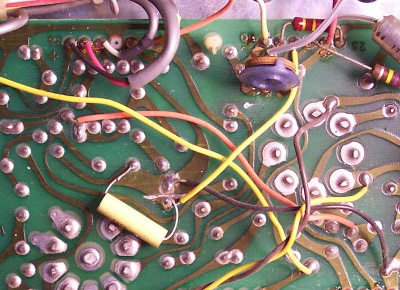 It increased the peak audio output of the tube. Slightly. But it became such a failure headache that we adopted the policy of removing that wire, soldering a jumper across the cut in the foil pad and putting back the missing resistors and C625 on the BA board. This restored the previous "cathode bias" setup and reduced the breakdowns after the customer got the radio back home. I know a longer explanation of this got posted here a few years ago. 73 |
|
|
|
Post by 2600 on Nov 3, 2019 23:52:40 GMT -5
|
|


