|
|
Post by No Streak on Jan 4, 2015 20:05:27 GMT -5
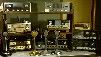
 Radio I picked up on Ebay 10 years ago. Only seen a picture of one on Kens Electronics before I bought this one. Not sure if they made it into production or the Super Satilite II. |
|
|
|
Post by cbrown on Jan 5, 2015 9:38:46 GMT -5
Never seen one of those before! Congratulations on your pickup.
|
|
|
|
Post by No Streak on Jan 5, 2015 11:15:23 GMT -5
Only wish I could find one Demco's answer to the Browning Mk IV Attachments:
|
|
|
|
Post by BBB on Jan 5, 2015 16:49:48 GMT -5
Didn't even know Demco made digital display radios, now I do. The buttons look like you can set it to scan in one-five minute increments?
|
|
|
|
Post by No Streak on Jan 5, 2015 17:25:17 GMT -5
The Demco Star II I have is a protype model so it mite have never been made. It is direct entry channel selection with full scan mode. It was dropped in shipping and had to get repairs done just to get it working again. But it does transmit and receive but low output power. As for the Super Satilite I never have seen one other than the picture. Sad it would have been neat to see one working.
|
|
Sandbagger
Administrator/The Boss 
Posts: 6,247 
|
Post by Sandbagger on Jan 5, 2015 21:09:34 GMT -5
The Demco Star II I have is a protype model so it mite have never been made. It is direct entry channel selection with full scan mode. It was dropped in shipping and had to get repairs done just to get it working again. But it does transmit and receive but low output power. As for the Super Satilite I never have seen one other than the picture. Sad it would have been neat to see one working. I take it that this radio is solid state and not tube? That radio reminds me of the Robyn SB540D. I have to wonder if the guts are the same..... |
|
|
|
Post by No Streak on Jan 5, 2015 21:41:56 GMT -5
Demco Star II is old school tube had it out a couple months ago. It like the 1960's one with up grades like the Yellow bird Robyn.It wasn't a Stoner Pro40 ,CPI 2000, ARF 2001 which were the top of the class.
|
|
Sandbagger
Administrator/The Boss
Posts: 6,247
|
Post by Sandbagger on Jan 5, 2015 22:20:43 GMT -5
Demco Star II is old school tube had it out a couple months ago. It like the 1960's one with up grades like the Yellow bird Robyn.It wasn't a Stoner Pro40 ,CPI 2000, ARF 2001 which were the top of the class. Wow, all that digital readout with scan and all that interfaced to a tube radio. Certainly not the first time that has been done, but probably the most elaborate use of it. Shame Demco never made it into the 80's. |
|
|
|
Post by No Streak on Jan 5, 2015 22:43:59 GMT -5
It mite have been a good thing Demco never made it into the 80's from the looks of the prototype. The Cobra 2000 GTL would have killed it anyway!
|
|
Sandbagger
Administrator/The Boss
Posts: 6,247
|
Post by Sandbagger on Jan 7, 2015 7:33:49 GMT -5
It mite have been a good thing Demco never made it into the 80's from the looks of the prototype. The Cobra 2000 GTL would have killed it anyway! Not if you're a tube enthusiast! The sad truth is that it is way too labor intensive to hand wire a tube radio. Even those that tried to utilize PC boards had a lot more labor involved to manufacture, so they ended up costing much more than solid state contemporaries. Companies like Browning, Tram, Demco and Sonar, known for their high quality tube radios, simply couldn't compete on a price basis with Japanese mass produced solid state rigs. And they all faded into the sunset in the 80's. And that ended a very special segment of CB radio history. |
|
|
|
Post by No Streak on Jan 7, 2015 11:58:40 GMT -5
And from understanding women did most if not all of the soldering on those radios. Browning and Tram both used PC boards with tubes mounted to them. But only Tram D201 suffered from broken traces on the boards due to overheating and undersized resisters heating up and burning out. Great radio Tram D201 but like with things engineering shortcuts cause problems later on.
|
|
Sandbagger
Administrator/The Boss
Posts: 6,247
|
Post by Sandbagger on Jan 7, 2015 13:04:43 GMT -5
And from understanding women did most if not all of the soldering on those radios. Browning and Tram both used PC boards with tubes mounted to them. But only Tram D201 suffered from broken traces on the boards due to overheating and undersized resisters heating up and burning out. Great radio Tram D201 but like with things engineering shortcuts cause problems later on. Well, one of the biggest issues with the D201, was the single HV voltage source. At 410V, it was great for modulator and RF amplifier power stages, but it was way too high for the small signal tubes. Dropping the B+ down to the level required for the small signal tubes required large power resistors which ran hot from all of the current they had to absorb from dropping over 200 volts, and they would change value over time. The heat also affected PC board tube sockets and there were often cold solder joints and lifted traces. The better way would have been to utilize a center tap on the HV secondary and run a separate supply line at 200V. That would have worked far better for the small signal tubes, requiring much less current drop in each individual dropping resistor. Much less heat would have been generated and resistor values would have drifted far less over time. |
|
|
|
Post by No Streak on Jan 8, 2015 9:14:01 GMT -5
Per Sparky's nice request I will take pictures of the inside of the Demco Star II , as I'm sure Dave you would also like to see the layup inside. Maybe see if I get a video of in operation.
|
|
Sandbagger
Administrator/The Boss
Posts: 6,247
|
Post by Sandbagger on Jan 8, 2015 17:06:32 GMT -5
Per Sparky's nice request I will take pictures of the inside of the Demco Star II , as I'm sure Dave you would also like to see the layup inside. Maybe see if I get a video of in operation. If it's not too much of an imposition for you to do that, I know *I* would love to see the insides of that very rare Demco. You definitely have a valuable gem there, and probably their last product.  |
|
|
|
Post by No Streak on Jan 8, 2015 17:06:45 GMT -5
|
|
Sandbagger
Administrator/The Boss
Posts: 6,247
|
Post by Sandbagger on Jan 9, 2015 7:36:13 GMT -5
Based on the "rough" looking appearance of the insides, I would have to concur that this definitely looks like a prototype or a pre-production unit. That actually makes it even more collectible, and potentially more valuable, especially if there were few or no productions units made. CB Tricks lists the model, but has no info on it. Thanks for taking those pics. Really cool...... |
|
|
|
Post by No Streak on Jan 9, 2015 8:17:15 GMT -5
Yeah I took a picture of the writing Prototype on the side of the chassis. I set it up and turned it on it wouldn't receive at first or transmit I'm oh crap its busted then it started to come back to life after about 10 minutes. I need to keep my eye out for a Demco Satillite super or not for my collection.There was nobody I know of that ran a Demco radio in my area.
I've been in cb radio since 1983 my dad had his cb that year a in dash car stereo cb unit and I was hooked, he was Blue Streak and was No Streak back then we talked on Channel 35. Sadly I never got my call sign they ended the year I got started into it .
|
|
Sandbagger
Administrator/The Boss
Posts: 6,247
|
Post by Sandbagger on Jan 9, 2015 9:22:54 GMT -5
Yeah I took a picture of the writing Prototype on the side of the chassis. I set it up and turned it on it wouldn't receive at first or transmit I'm oh crap its busted then it started to come back to life after about 10 minutes. I need to keep my eye out for a Demco Satillite super or not for my collection.There was nobody I know of that ran a Demco radio in my area. I've been in cb radio since 1983 my dad had his cb that year a in dash car stereo cb unit and I was hooked, he was Blue Streak and was No Streak back then we talked on Channel 35. Sadly I never got my call sign they ended the year I got started into it . You're not alone. I've never known anyone "back in the day" in my local area who ran a Demco radio. I once had an original Satellite in my possession back in 1975, that the owner wanted me to go through and make sure everything was ok before he sold it. I was given the accessory wattmeter as partial payment for tuning it up. But that was the only one I ever knew of. Most of the CB'ers in my area got into the hobby in the late 60's or early 70's and ran mostly newer solid state radios. Ironically a lot of the younger guys ended up with the hand-me-down, second hand tube rigs because it was all we could afford. |
|
|
|
Post by cbrown on Jan 9, 2015 10:50:39 GMT -5
Based on the "rough" looking appearance of the insides, I would have to concur that this definitely looks like a prototype or a pre-production unit. That actually makes it even more collectible, and potentially more valuable, especially if there were few or no productions units made. CB Tricks lists the model, but has no info on it. Thanks for taking those pics. Really cool...... I agree, and thanks for the photos! |
|
|
|
Post by BBB on Jan 10, 2015 10:34:12 GMT -5
|
|
|
|
Post by No Streak on Jan 10, 2015 13:35:11 GMT -5
Yeah I'm finding that Demco radios are hard to come by or rusted face plates. It's sad to see them type of shape.
|
|
|
|
Post by No Streak on Jan 13, 2015 20:35:04 GMT -5
Well tomorrow night is Classic Radio Roundup, I wonder if SpitFire is going to have his Demco SUPER Satellite ready for operation?
|
|
Sandbagger
Administrator/The Boss
Posts: 6,247
|
Post by Sandbagger on Jan 13, 2015 20:43:38 GMT -5
Well tomorrow night is Classic Radio Roundup, I wonder if SpitFire is going to have his Demco SUPER Satellite ready for operation? I believe so. He was just remarking that he's solved its issues and it's screamin' loud now. So if you tune in tomorrow night, I'm sure you'll hear it. |
|
|
|
Post by No Streak on Jan 13, 2015 20:58:56 GMT -5
Sounds good it will be great to hear it on the air again,I think it's been quite awhile since it has been on the roundup!  |
|
Sandbagger
Administrator/The Boss
Posts: 6,247
|
Post by Sandbagger on Jan 13, 2015 21:50:56 GMT -5
Sounds good it will be great to hear it on the air again,I think it's been quite awhile since it has been on the roundup! View AttachmentI may have spoken too soon. He had it on the air briefly and it was throwing spurs out all over the band and sounded generally rough. Something's still out of whack...... I figure I'll be answering questions, so I printed out the schematic to have on hand..... |
|
|
|
Post by spitfire441 on Jan 14, 2015 6:45:06 GMT -5
Sounds good it will be great to hear it on the air again,I think it's been quite awhile since it has been on the roundup! View AttachmentI may have spoken too soon. He had it on the air briefly and it was throwing spurs out all over the band and sounded generally rough. Something's still out of whack...... I figure I'll be answering questions, so I printed out the schematic to have on hand..... Since you have the schematic handy. What is the purpose of the neon bulb between V1A plate and V1B just before the IF can? The one leg is broken off at the glass and I don't think there is enough to solder to. I wonder if that is giving me problems with tuning out spurs. I feel the radio is very close to being right. I have good audio waveform but spurs on "spec any-lizer" They are more than 40 db down, but I feel I should be able to do better as there seems to be too many. Also what is the reason for that 220 ohm resistor off pin 5 of V1? BTW the CB tricks scematic doesn't have it. Spitfire 441 County Wide Radio LLC |
|
|
|
Post by No Streak on Jan 14, 2015 6:58:17 GMT -5
Well Pete I hope you can work out the bugs and get her working again with all the Demco glory.
|
|
Sandbagger
Administrator/The Boss
Posts: 6,247
|
Post by Sandbagger on Jan 14, 2015 8:17:48 GMT -5
I may have spoken too soon. He had it on the air briefly and it was throwing spurs out all over the band and sounded generally rough. Something's still out of whack...... I figure I'll be answering questions, so I printed out the schematic to have on hand..... Since you have the schematic handy. What is the purpose of the neon bulb between V1A plate and V1B just before the IF can? The one leg is broken off at the glass and I don't think there is enough to solder to. I wonder if that is giving me problems with tuning out spurs. I feel the radio is very close to being right. I have good audio waveform but spurs on "spec any-lizer" They are more than 40 db down, but I feel I should be able to do better as there seems to be too many. Also what is the reason for that 220 ohm resistor off pin 5 of V1? BTW the CB tricks scematic doesn't have it. Spitfire 441 County Wide Radio LLC Not sure what the exact purpose of that neon bulb is. They typically fire at about 60V which is what should be on the plate. It could be a sort of transient suppressor, or a voltage clamp but it's not frequency sensitive, so it shouldn't affect in-band spurs. What you DO need to set is the neutralization cap. Generally this is adjusted by removing plate voltage from the final (Point "B" marked on the schematic), and then keying the transmitter and tuning the neutralization cap for minimum output, then repeaking the tuning coil (which is curiously not marked) between the driver and final tubes for maximum, and then back to the neutralizing cap for minimum. Keep going back and forth between those two adjustments until no further change is noticed. Because you've removed plate voltage, the radio won't put out any "watts", so you'll have to use your spectrum analyzer probe on the antenna jack to see the signal. Once you're neutralized, you should be able to re-connect the plate supply and not have any spurs. I also don't know why there is a resistor across the tube filaments. It's not marked on the schematic, so I have to wonder why it's there and whether someone added it for some reason. |
|
|
|
Post by spitfire441 on Jan 14, 2015 9:28:43 GMT -5
Since you have the schematic handy. What is the purpose of the neon bulb between V1A plate and V1B just before the IF can? The one leg is broken off at the glass and I don't think there is enough to solder to. I wonder if that is giving me problems with tuning out spurs. I feel the radio is very close to being right. I have good audio waveform but spurs on "spec any-lizer" They are more than 40 db down, but I feel I should be able to do better as there seems to be too many. Also what is the reason for that 220 ohm resistor off pin 5 of V1? BTW the CB tricks scematic doesn't have it. Spitfire 441 County Wide Radio LLC Not sure what the exact purpose of that neon bulb is. They typically fire at about 60V which is what should be on the plate. It could be a sort of transient suppressor, or a voltage clamp but it's not frequency sensitive, so it shouldn't affect in-band spurs. What you DO need to set is the neutralization cap. Generally this is adjusted by removing plate voltage from the final (Point "B" marked on the schematic), and then keying the transmitter and tuning the neutralization cap for minimum output, then repeaking the tuning coil (which is curiously not marked) between the driver and final tubes for maximum, and then back to the neutralizing cap for minimum. Keep going back and forth between those two adjustments until no further change is noticed. Because you've removed plate voltage, the radio won't put out any "watts", so you'll have to use your spectrum analyzer probe on the antenna jack to see the signal. Once you're neutralized, you should be able to re-connect the plate supply and not have any spurs. I also don't know why there is a resistor across the tube filaments. It's not marked on the schematic, so I have to wonder why it's there and whether someone added it for some reason. Thanks for the input. I'll do the neutralization later today and see what I can achieve. I am on the search for another neon bulb, I think Blockhead may be able to help me on that score. That 220 ohm resistor IS on my Demco schematic that is in the original manual I have. Although it does not include a parts list. I does look factory, but who knows. It not factory anymore as I have replaced it. 441, The Spitfire |
|
Sandbagger
Administrator/The Boss
Posts: 6,247
|
Post by Sandbagger on Jan 14, 2015 9:41:58 GMT -5
Not sure what the exact purpose of that neon bulb is. They typically fire at about 60V which is what should be on the plate. It could be a sort of transient suppressor, or a voltage clamp but it's not frequency sensitive, so it shouldn't affect in-band spurs. What you DO need to set is the neutralization cap. Generally this is adjusted by removing plate voltage from the final (Point "B" marked on the schematic), and then keying the transmitter and tuning the neutralization cap for minimum output, then repeaking the tuning coil (which is curiously not marked) between the driver and final tubes for maximum, and then back to the neutralizing cap for minimum. Keep going back and forth between those two adjustments until no further change is noticed. Because you've removed plate voltage, the radio won't put out any "watts", so you'll have to use your spectrum analyzer probe on the antenna jack to see the signal. Once you're neutralized, you should be able to re-connect the plate supply and not have any spurs. I also don't know why there is a resistor across the tube filaments. It's not marked on the schematic, so I have to wonder why it's there and whether someone added it for some reason. Thanks for the input. I'll do the neutralization later today and see what I can achieve. I am on the search for another neon bulb, I think Blockhead may be able to help me on that score. That 220 ohm resistor IS on my Demco schematic that is in the original manual I have. Although it does not include a parts list. I does look factory, but who knows. It not factory anymore as I have replaced it. 441, The Spitfire I should have a neon bulb or two, if nothing else. I'll just have to find them...... |
|