|
|
Post by husker on Nov 24, 2017 0:37:56 GMT -5
I had this fixed bias setup, I followed the "fix" by removing the 10 ohm resistor and the yellow wire, then jumping the trace back at the cut. When I fired up the radio...zero audio. Any ideas?
|
|
Sandbagger
Administrator/The Boss 
Posts: 6,247 
|
Post by Sandbagger on Nov 24, 2017 11:16:15 GMT -5
I had this fixed bias setup, I followed the "fix" by removing the 10 ohm resistor and the yellow wire, then jumping the trace back at the cut. When I fired up the radio...zero audio. Any ideas? Did you have audio before you made the changes? |
|
|
|
Post by husker on Nov 24, 2017 11:22:34 GMT -5
yes sir, AM was not very good, but SSB was great
|
|
Sandbagger
Administrator/The Boss
Posts: 6,247
|
Post by Sandbagger on Nov 24, 2017 11:38:20 GMT -5
yes sir, AM was not very good, but SSB was great I'm a little confused by the 10 ohm resistor removal. I don't recall one involved with the audio power tube. However, there is a 10 ohm from the cathode to ground on the RF final tube, which Tram went to when they switched from the 6L6 to the 6DG6 final tube. That resistor should be jumpered across when going back to a 6L6. On the audio tube, restoring the cut on the circuit trace, removal of the yellow wire, and adding the self bias resistors, fuse, and cathode bypass capacitor back on the BA board needs to be done to convert back to self bias from fixed bias. The audio/modulator works on receive in both AM and SSB modes, but only provides AM transmit audio. SSB TX audio is low level, and does not utilize the audio output tube. |
|
|
|
Post by husker on Nov 24, 2017 12:13:27 GMT -5
As am I, the 100,000 mile check up states to remove it and place a jumper in it's place. The manual I have doesn't show a resistor there, but both my 201a's have i there. Both run the 6L6 tube on the audio brd. The only thing that still is different from the stock config is this resistor.
|
|
Sandbagger
Administrator/The Boss
Posts: 6,247
|
Post by Sandbagger on Nov 24, 2017 20:02:22 GMT -5
As am I, the 100,000 mile check up states to remove it and place a jumper in it's place. The manual I have doesn't show a resistor there, but both my 201a's have i there. Both run the 6L6 tube on the audio brd. The only thing that still is different from the stock config is this resistor. Just so we're talking about the same thing, where exactly is this 10 ohm resistor located? Is it on the audio output tube, or the RF final output tube? Which pins? |
|
|
|
Post by husker on Nov 24, 2017 22:22:05 GMT -5
Correct, in back of the audio 6L6GC
|
|
Sandbagger
Administrator/The Boss
Posts: 6,247
|
Post by Sandbagger on Nov 25, 2017 17:56:45 GMT -5
Correct, in back of the audio 6L6GC And that is the source of my confusion. As far as I know, there is no 10 Ohm resistor anywhere near the audio output tube. However, there is a 10 ohm resistor on the RF output tube from the cathode to ground, which was incorporated when they changed from the original 6L6 design to the 6DG6 in the D201a. Jumping that resistor out is part of the mod to return to a 6L6. But that is on the RF output tube, not the audio tube, and it does not have anything to do with the fixed bias setup. |
|
|
|
Post by husker on Nov 26, 2017 0:52:26 GMT -5
lol, I see now. No, I didn't do the 10 Ohm removal for the bias, I did it following the 100,000 mile check up sheet. My point was that was the only other thing I did besides clip the yellow wire and jump the trace cut. Am I making better sense now?
|
|
Sandbagger
Administrator/The Boss
Posts: 6,247
|
Post by Sandbagger on Nov 26, 2017 9:24:06 GMT -5
lol, I see now. No, I didn't do the 10 Ohm removal for the bias, I did it following the 100,000 mile check up sheet. My point was that was the only other thing I did besides clip the yellow wire and jump the trace cut. Am I making better sense now? Did you also (re)install the self bias resistors on the BA board? |
|
|
|
Post by husker on Nov 26, 2017 12:28:26 GMT -5
I never removed them. See, part of whatr was confusing and may have lead to more issues in different ares (?) was I followed the simple instructions of the 100,000 check list I attached to a previous thread. That is all on me, I should have asked for more information prior to removing anything. So my BA brd didn't have any jumpers, it has all the resistors in place. Also, the BA brd has been redone as have the two multi-section caps. So at this point the radio is back to square one, but I have added the missing resistor I found gone and replaced a couple others that looked over heated. So,  ...help please lol..the tubes have been checked (actually replaced a couple with known good ones) and they appear to be good. Any thoughts as to why I get no audio? It's like looking for a needle in a haystack sadly |
|
|
|
Post by 2600 on Nov 26, 2017 16:01:19 GMT -5
Umm, okay Husker. I went back through the posts in this thread, and I can't find the problem you're having.
Lost transmit audio?
Receive?
Maybe I missed the post with this detail.
73
|
|
|
|
Post by husker on Nov 26, 2017 16:09:04 GMT -5
Hi! So the original issue was a lack of AM receive. Then I tried something I shouldn't have without a better understanding of what I was doing ( the fixed bias change of cutting the yellow wire and the jumper of the cut trace, and my BA brd didn't have the jumpers to begin with ) and now I have zero receive audio. HELP lol
|
|
Sandbagger
Administrator/The Boss
Posts: 6,247
|
Post by Sandbagger on Nov 26, 2017 18:44:56 GMT -5
I never removed them. See, part of whatr was confusing and may have lead to more issues in different ares (?) was I followed the simple instructions of the 100,000 check list I attached to a previous thread. That is all on me, I should have asked for more information prior to removing anything. So my BA brd didn't have any jumpers, it has all the resistors in place. Also, the BA brd has been redone as have the two multi-section caps. So at this point the radio is back to square one, but I have added the missing resistor I found gone and replaced a couple others that looked over heated. So, ...help please lol..the tubes have been checked (actually replaced a couple with known good ones) and they appear to be good. Any thoughts as to why I get no audio? It's like looking for a needle in a haystack sadly That's what doesn't make sense. If the radio was originally equipped with the fixed bias mod from the factory, it should also have been equipped with a BA board that replaced the original resistors with jumpers. You're saying that the the resistors on the BA board are still there? Was that BA board possibly from another radio? Is the fuse on the BA board good? Also don't understand the comment about multi section caps on the BA board. The BA board is the plug-in board next to the audio output tube. There are no multi-section caps on it. Only low voltage caps for the 14V regulator, a .22uF filter for the relay circuit, and a 4 uF bypass cap for the audio driver tube. |
|
|
|
Post by 2600 on Nov 26, 2017 22:51:34 GMT -5
Does your BA board have a fuse on it?
The factory-supplied 1/10-Amp fuse (100 mA) has an incredibly thin element. If a continuity test says it's okay, this isn't the problem.
Just can't trust the calibrated eyeball alone.
If this fuse trips, you will have no audio at all, AM or SSB, neither transmit nor receive.
If you are missing audio on only one mode, like AM (and NOT SSB) your problem is NOT located on the audio board. Receive audio for ALL modes is delivered to the audio board from the mode selector. A fault on the audio board will affect all receive modes equally.
A loss of just AM or SSB receiver audio will reside on the main receiver board, or the mode selector and its wiring.
Never, every assume that a 40 year-old radio has JUST ONE problem at any given time. The odds don't favor it.
Avoid the temptation to use a fuse bigger than 1/8 Amp, or 125 mA. We find that the original 1/10-Amp size can be tripped from overmodulation alone. The bigger the fuse, the more smoke gets released in the event of a fault. The more smoke you let out, the more it costs to put back in.
Won't work until enough fresh smoke is installed.
73
|
|
|
|
Post by husker on Nov 27, 2017 22:07:00 GMT -5
OMG!!! lol, I couldnt agree more |
|
|
|
Post by husker on Nov 28, 2017 0:03:02 GMT -5
Does your BA board have a fuse on it? The factory-supplied 1/10-Amp fuse (100 mA) has an incredibly thin element. If a continuity test says it's okay, this isn't the problem. Just can't trust the calibrated eyeball alone. If this fuse trips, you will have no audio at all, AM or SSB, neither transmit nor receive. If you are missing audio on only one mode, like AM (and NOT SSB) your problem is NOT located on the audio board. Receive audio for ALL modes is delivered to the audio board from the mode selector. A fault on the audio board will affect all receive modes equally. A loss of just AM or SSB receiver audio will reside on the main receiver board, or the mode selector and its wiring. Never, every assume that a 40 year-old radio has JUST ONE problem at any given time. The odds don't favor it. Avoid the temptation to use a fuse bigger than 1/8 Amp, or 125 mA. We find that the original 1/10-Amp size can be tripped from overmodulation alone. The bigger the fuse, the more smoke gets released in the event of a fault. The more smoke you let out, the more it costs to put back in. Won't work until enough fresh smoke is installed. 73 Ok, but I shouldn't have a fuse on the BA brd if I have a fixed bias should I? I just have jumpers. It is both AM and SSB, no receive. So you would look at the mode selector? |
|
|
|
Post by husker on Dec 1, 2017 23:42:27 GMT -5
Does your BA board have a fuse on it? The factory-supplied 1/10-Amp fuse (100 mA) has an incredibly thin element. If a continuity test says it's okay, this isn't the problem. Just can't trust the calibrated eyeball alone. If this fuse trips, you will have no audio at all, AM or SSB, neither transmit nor receive. If you are missing audio on only one mode, like AM (and NOT SSB) your problem is NOT located on the audio board. Receive audio for ALL modes is delivered to the audio board from the mode selector. A fault on the audio board will affect all receive modes equally. A loss of just AM or SSB receiver audio will reside on the main receiver board, or the mode selector and its wiring. Never, every assume that a 40 year-old radio has JUST ONE problem at any given time. The odds don't favor it. Avoid the temptation to use a fuse bigger than 1/8 Amp, or 125 mA. We find that the original 1/10-Amp size can be tripped from overmodulation alone. The bigger the fuse, the more smoke gets released in the event of a fault. The more smoke you let out, the more it costs to put back in. Won't work until enough fresh smoke is installed. 73 Ok, so I decided to do a little old fashion trouble shooting, not knowing nearly what many of you know, but never the less try. I was testing resistors (R3&4) and I happened to touch R6, the big 100ohm 7 watt resistor. Well, to my surprise it was loose, I touched it and one end came up in my hand. it appears that one leg wasn't connected fully through the hole in the brd or it had come loose. It looked a tad worse for wear, so I went ahead and ordered a new one. I can only assume this not being connected would lead to some pretty interesting audio issues? |
|
|
|
Post by 2600 on Dec 2, 2017 0:23:25 GMT -5
If that one comes loose everything stops working.
73
|
|
|
|
Post by husker on Dec 2, 2017 2:25:21 GMT -5
well,when I was trying to test voltage on different parts, the power was erratic, it would read say 452 volts, then drop to almost nothing then come back, I wonder if this resistor was loose and would touch off and on to give me those voltage readings?
|
|
Sandbagger
Administrator/The Boss
Posts: 6,247
|
Post by Sandbagger on Dec 2, 2017 10:56:51 GMT -5
Does your BA board have a fuse on it? The factory-supplied 1/10-Amp fuse (100 mA) has an incredibly thin element. If a continuity test says it's okay, this isn't the problem. Just can't trust the calibrated eyeball alone. If this fuse trips, you will have no audio at all, AM or SSB, neither transmit nor receive. If you are missing audio on only one mode, like AM (and NOT SSB) your problem is NOT located on the audio board. Receive audio for ALL modes is delivered to the audio board from the mode selector. A fault on the audio board will affect all receive modes equally. A loss of just AM or SSB receiver audio will reside on the main receiver board, or the mode selector and its wiring. Never, every assume that a 40 year-old radio has JUST ONE problem at any given time. The odds don't favor it. Avoid the temptation to use a fuse bigger than 1/8 Amp, or 125 mA. We find that the original 1/10-Amp size can be tripped from overmodulation alone. The bigger the fuse, the more smoke gets released in the event of a fault. The more smoke you let out, the more it costs to put back in. Won't work until enough fresh smoke is installed. 73 Ok, so I decided to do a little old fashion trouble shooting, not knowing nearly what many of you know, but never the less try. I was testing resistors (R3&4) and I happened to touch R6, the big 100ohm 7 watt resistor. Well, to my surprise it was loose, I touched it and one end came up in my hand. it appears that one leg wasn't connected fully through the hole in the brd or it had come loose. It looked a tad worse for wear, so I went ahead and ordered a new one. I can only assume this not being connected would lead to some pretty interesting audio issues? That resistor is in the main 410V B+ power supply line. If that is open, none of the circuits will get power. I would make sure that all connections are solid in that area. The amount of heat that a D201 generates in those power resistors can often lead to traces lifting and cold solder joints. Broken connections will stop the rig cold in its tracks. |
|
|
|
Post by husker on Dec 5, 2017 0:27:58 GMT -5
ok, so I have replaced all the caps, all "problematic" resistors, checked tubes. Everything checks out, but still no audio. Couple questions, I do have a re built audio brd I could swap in, but man that's a lot of work. And second, how would I know of I did indeed have a bad mode switch? That's even more fun to swap out by the looks of it!
thanks guys!
|
|
Sandbagger
Administrator/The Boss
Posts: 6,247
|
Post by Sandbagger on Dec 5, 2017 15:04:06 GMT -5
ok, so I have replaced all the caps, all "problematic" resistors, checked tubes. Everything checks out, but still no audio. Couple questions, I do have a re built audio brd I could swap in, but man that's a lot of work. And second, how would I know of I did indeed have a bad mode switch? That's even more fun to swap out by the looks of it! thanks guys! I'm typically not a fan of the "shotgun" approach to troubleshooting. Before you start replacing audio boards, you should try checking voltages on the tubes and then injecting an audio signal starting at the volume control and tracing it back through the stages. Also make sure your speaker isn't open if you are checking receive. |
|
|
|
Post by 2600 on Dec 6, 2017 22:30:12 GMT -5
I got a pm from Husker, reporting this:
BA brd, I am getting high voltages on
PIN 8 450v
PIN 9 445v
PIN 10 450 v
Pin 8 is the high B+ voltage, normally shown on the diagram as +410 Volts. But if the audio tube is not drawing the normal current, this reading will run higher.
Pin 9 is feeding the hot side of the relay coil. In receive mode, the relay is turned off, and this reading is probably about right.
Pin 10 feeds the screen grid pin 4 of V603, the 6L6GC audio power tube. If the tube is not drawing normal current, this reading will be higher than the 385 Volts shown on the schematic.
And this is where fixed bias on the 6L6 makes troubleshooting more trouble. If the BA board had the cathode-bias resistors on it, the reading at pin 12 would tell us how much current that tube is drawing.
But the fixed-bias version has only jumper wires to ground on pin 12. Makes the correct reading about zero.
But there should be a 10-ohm resistor at the R640 spot on the main audio board. This resistor connects to pin 8 of the 6L6. A voltage drop of 6/10 of a Volt (600 mV) is the reading you should have with the fixed-bias trimpot set correctly. That reading would tell you that the tube is drawing 60 mA of current. Multiply that times the 400 Volts across the tube, and you get a steady heat dissipation of 24 Watts on that tube. We tended to set it for half a Volt, (50 mA) with the assumption that this reading tends to creep up with the passage of time. Seemed safer for the radio's owner that way.
If you have a reading very different from that at pin 8 of V602, this would be informative. But the readings at pin 8,9 and 10 of the BA board are more suggestive, and less informative by themselves.
73
|
|
|
|
Post by husker on Dec 9, 2017 2:19:58 GMT -5
I am getting a reading of -2.9 volts on pin 8 of v603. I had to remove the tube as something is making it cherry. I removed the 10 ohm that was behind v603 and jumped it. I am also reading -2.9 on pin 57.
The crazy current draw (including bad hum) and the over heating 6l6 worries me.
Do you by any chance have the amendment for the fixed bias version? I was told there was an amendment schematic?
|
|
Sandbagger
Administrator/The Boss
Posts: 6,247
|
Post by Sandbagger on Dec 9, 2017 17:45:21 GMT -5
I am getting a reading of -2.9 volts on pin 8 of v603. I had to remove the tube as something is making it cherry. I removed the 10 ohm that was behind v603 and jumped it. I am also reading -2.9 on pin 57. The crazy current draw (including bad hum) and the over heating 6l6 worries me. Do you by any chance have the amendment for the fixed bias version? I was told there was an amendment schematic? Did you re-install the cathode (self bias) resistors back on the BA board? |
|
|
|
Post by husker on Dec 9, 2017 17:46:50 GMT -5
I never removed them on this BA brd. I have a few extras and I was using a non fixed bias BA when I attempted to change the bias.
|
|
Sandbagger
Administrator/The Boss
Posts: 6,247
|
Post by Sandbagger on Dec 10, 2017 10:20:15 GMT -5
I never removed them on this BA brd. I have a few extras and I was using a non fixed bias BA when I attempted to change the bias. Is there a 10 ohm resistor from the cathode (pin 8) of the tube directly to ground? If so, that needs to be removed. If that resistor is in the spot marked R640, it needs to be replaced with an 82 ohm resistor. That should bring things back to the original D201 era self bias scheme. |
|
|
|
Post by wildcat444 on Oct 10, 2020 18:28:03 GMT -5
This is our solution to BA board problems. 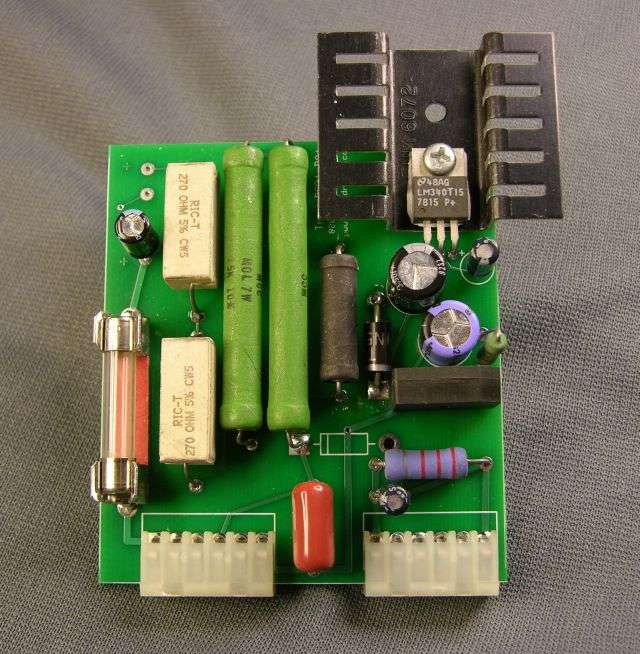 2600, I am restoring my 23ch PCB version D201. I have been choosing all the high watt resistors and electrolytic caps from Mouser, but don't see the Q1 regulator at Mouser. I see you use an LM240T15 on your board. This is available at Mouser, but your board looks custom. I wanted to ask if this regulator would work for Q1 in my factory board? If so, I assume you cut the middle ground leg and let the ground come from the metal mounting of the TO-220 package? If not, can anyone offer a suitable replacement for Q1 I can find at Mouser for the 23 ch version which I think is the earlier BA board? I see them at Digikey, but I don't want to order one single part from there and end up with a total of around $15 for a $2 part when you add shipping. Thanks! |
|
|
|
Post by 2600 on Oct 10, 2020 23:47:48 GMT -5
I don't want to order one single part from there and end up with a total of around $15 for a $2 part when you add shipping. And there's the problem. Everyone who used to make "just one" part (or two) available for you to walk in and buy has gone extinct. Everything comes from a supplier half across the country, or halfway across the planet. I used to quote a price to ship an empty box, plus whatever gets put in it. But we don't sell parts retail, beyond what we list on fleabay. There's no business model to stock electronic parts and sell small quantities. Costs are too high, markup and volume both too low. And yes, the board is our custom design. Sold a few to other techs, but mostly we use them for the repair business here. Reduces the number of built-in "weak spots" that could cause trouble after we send the radio home. 73 |
|


 ...help please lol..the tubes have been checked (actually replaced a couple with known good ones) and they appear to be good.


