Deleted
Deleted Member
Posts: 0
|
Post by Deleted on Jan 11, 2009 21:45:57 GMT -5
Does anyone have this? This is for the Saturn, not the Turbo. My friend brought it over to adjust his claifier on center. Pretty easy from the manual. But when he tried it, his transmit and receive are off.
|
|
Sandbagger
Administrator/The Boss 
Posts: 6,250 
|
Post by Sandbagger on Jan 11, 2009 22:25:51 GMT -5
Does anyone have this? This is for the Saturn, not the Turbo. My friend brought it over to adjust his claifier on center. Pretty easy from the manual. But when he tried it, his transmit and receive are off. That's probably because the coarse clarifier is unlocked, while the fine is not. The fine transmit frequency center is controlled by a pot inside the radio similar to a standard CB setup. If you set the fine clarifier on receive for center, you have to set the internal pot to match, or you can unlock the fine clarifier similar to how you'd do it in a standard CB.. |
|
Deleted
Deleted Member
Posts: 0
|
Post by Deleted on Jan 11, 2009 22:31:26 GMT -5
I want to make sure I have the right procedure. What are the sister radios?
|
|
|
|
Post by 2600 on Jan 11, 2009 23:44:47 GMT -5
Didn't I post that here already?
Which pc board does this radio have?
If it's a EPT3600-14, I think it's here, somewhere. Pretty simple. Pull one diode, pull out one (only) wire of a resistor and put it into an empty hole next to where it came out.
I'll see if I can dig it up.
73
|
|
Deleted
Deleted Member
Posts: 0
|
Post by Deleted on Jan 11, 2009 23:51:18 GMT -5
I have to get the radio. The manual I have shows different schematics and component layout. This is a local who I am friends with. It is his main radio. The radio he had has the 4 cans for L22, L21, L20, L19 toward the front, slightly left of center . The manual I have does not have L22. The diodes and resistor are in different places.
|
|
|
|
Post by 2600 on Jan 11, 2009 23:55:25 GMT -5
The search here turns up squat. Odd. Here's the setup for the "14A" and later pc boards. 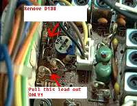 And step 2:  As a rule, you'll still need to set the channel-center trimmer coils after doing this. If your main board is older, find the EPT number and I'll see if I have anything specific to the old boards. Don't see that many of them here any more. 73 |
|
Deleted
Deleted Member
Posts: 0
|
Post by Deleted on Jan 12, 2009 9:53:25 GMT -5
Thanks. He brought it over tonight. It was a 14B board, and the mod was not done. I did it and adjust the coils.
The only thing is the diode is label D38, not D138.
|
|
|
|
Post by 2600 on Jan 12, 2009 23:55:52 GMT -5
Oops...
73
|
|
Deleted
Deleted Member
Posts: 0
|
Post by Deleted on Jan 13, 2009 8:46:52 GMT -5
No biggie. The pictures were perfect. It was obvious what components you meant.
BTW, the limiter was clipped on this radio. I offered to reconnect it. He refused. Would this cause warbling on SSB?
|
|
|
|
Post by Tombstone (R.I.P.) on Jan 13, 2009 18:43:00 GMT -5
Defeating modulation limiters is usually not good unless even after trying a power mic that that's the only way to get the modulation up to snuff but a low modulation symptom usually indicates another problem somewhere. He should have let you put the limiter back to factory. I guess that clipping limiters could cause warbling.
Tombstone
|
|
Sandbagger
Administrator/The Boss
Posts: 6,250
|
Post by Sandbagger on Jan 13, 2009 22:32:57 GMT -5
No biggie. The pictures were perfect. It was obvious what components you meant. BTW, the limiter was clipped on this radio. I offered to reconnect it. He refused. Would this cause warbling on SSB? A lot of times when you crank open the ALC (which would happen if the main limiter transistor was "clipped"), you cause the radio's power to jump up which in turn causes a bigger drain on the power supply. When the supply voltage drops, the oscillator drifts in sync with the power peaks. We commonly refer to that as "FM'ing". There are a number of things that can cause this though. Sometimes the 8V regulator goes bad and the PLL voltage jumps up to 10 or 11 V. With less regulation, there is more warble. Also if someone tried to extend the clarifier range by tying the hot side to a higher (and less regulated) voltage source, that could also cause warble. And last buy not least, poor grounds or missing shields can allow RF to "leak" back into the PLL where it can demodulate and ride on the VCO voltage again, causing warble. This can be a real pain in the ass to find depending on the radio. But in many cases, if there are no obvious signs (like what I mentioned above) just setting the radio back to stock power can usually minimize it. |
|


