|
|
Post by homerbb on Mar 30, 2012 8:45:17 GMT -5
|
|
|
|
Post by Night Ranger on Mar 30, 2012 8:58:00 GMT -5
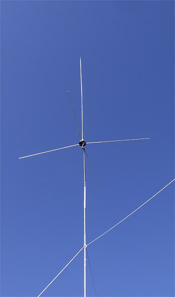
.64 wave ground plane antennas kick butt. My favorite omni antenna was the old Radio Shack .64 wave ground plane.
Night Ranger
|
|
|
|
Post by cbrown on Mar 30, 2012 9:11:34 GMT -5
You knew I was going to ask about the bandwidth. ;D Very impressive, almost 3.5 MHz!
Usually raising an antenna higher will reduce any SWR problems you may have (getting it away from any other influences as it were).
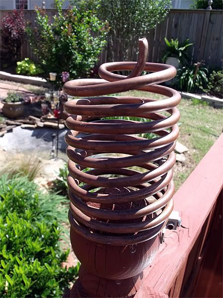
It's a nice design, and I like the wide tapped coil. Very nice. What do you think it would cost to make?
|
|
Sandbagger
Administrator/The Boss 
Posts: 6,250 
|
Post by Sandbagger on Mar 30, 2012 19:25:20 GMT -5
While it may make only the slightest of differences, using a coil for impedence matching tends to be lossier than a trombone, beta or gamma matches, at least according to tests I've seen. Back when Jay in the Mojave was designing the I-10K, he tried a few different matching methods before he chose the trombone match, which he picked dues to best signal radiation. |
|
|
|
Post by homerbb on Mar 30, 2012 20:44:32 GMT -5
I've never made a trombone, but I may have to try it.
|
|
|
|
Post by homerbb on Mar 31, 2012 11:30:55 GMT -5
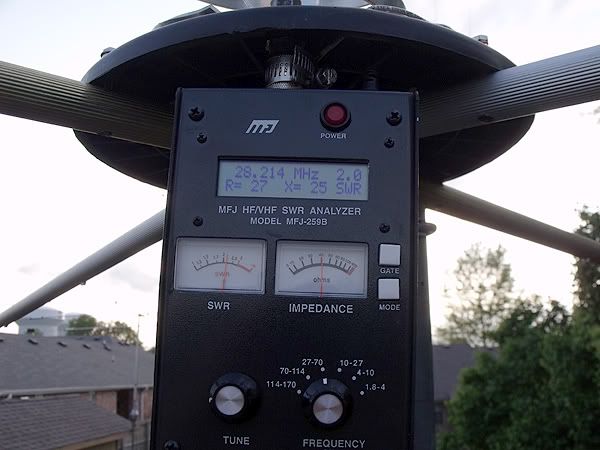
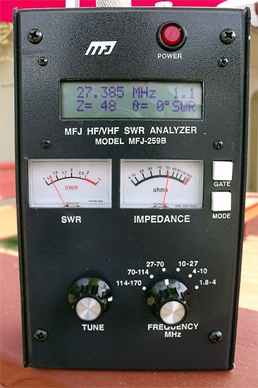
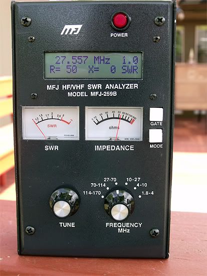
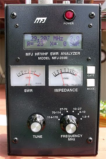
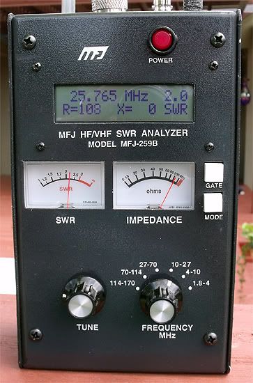
You knew I was going to ask about the bandwidth. ;D Very impressive, almost 3.5 MHz! Usually raising an antenna higher will reduce any SWR problems you may have (getting it away from any other influences as it were). It's a nice design, and I like the wide tapped coil. Very nice. What do you think it would cost to make? I haven't sat down to figure it out. Some things I already had, and others I bought. Some were free. however I'd guess around the $90 range at the most. Some questions have arisen regarding the bandwidth of this antenna on other forums, so I retested and photographed the series of analyzer readings this morning. Before hand I discovered a poorly soldered coax end and repaired it.
So here they are in the increments of interest, I hope, starting with the highest 2.0:1 frequency.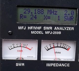 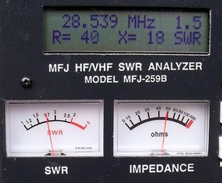 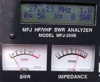 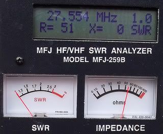 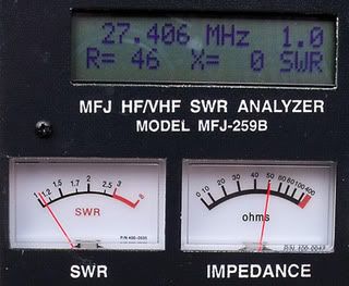 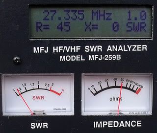 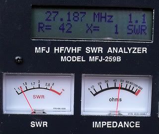 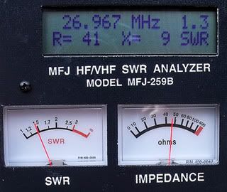 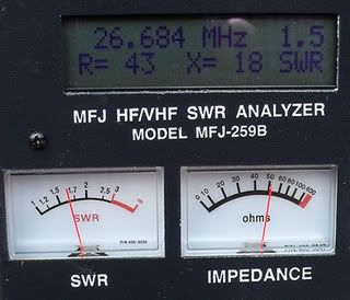 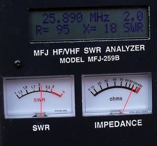 Each reading represents where I first and last encountered these particular readings as I went down the bands - 2.0, 1.5, 1.0 - and T5, .405, .185, and .965. Maybe there is more info regarding X= shifts along the SWR curve. Each reading represents where I first and last encountered these particular readings as I went down the bands - 2.0, 1.5, 1.0 - and T5, .405, .185, and .965. Maybe there is more info regarding X= shifts along the SWR curve.
All readings were done in the main mode only.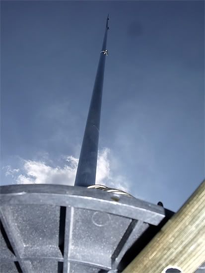 |
|
|
|
Post by cbrown on Apr 2, 2012 8:41:43 GMT -5
While it may make only the slightest of differences, using a coil for impedence matching tends to be lossier than a trombone, beta or gamma matches, at least according to tests I've seen. Back when Jay in the Mojave was designing the I-10K, he tried a few different matching methods before he chose the trombone match, which he picked dues to best signal radiation. And tuning is a breeze with the trombone design, too. I can match SWR and impedance to where I want. I really like Jay's design. |
|
|
|
Post by homerbb on Apr 2, 2012 8:52:43 GMT -5
I have no doubt that is true. Yet, ironically, I've heard someone else say they never could get their I10k tuned flat.
|
|
|
|
Post by homerbb on Apr 2, 2012 22:23:20 GMT -5
I moved the antenna up just 5 more feet to 13' from the ground. The SWR curve slid down the band, and a preliminary look at the numbers seem to indicate a narrowing of the bandwidth, but I'm not sure yet. I did not have time to check it carefully.
Perhaps my theorizing ground losses affecting the readings on the low mounted antenna have merit. . . I will retune for match then check it out some more.
|
|
|
|
Post by cbrown on Apr 3, 2012 8:44:55 GMT -5
I have no doubt that is true. Yet, ironically, I've heard someone else say they never could get their I10k tuned flat. Could be their coax. I also use a MFJ-259B and I can get the I10K tuned flat. My only complaint would be that it does have a narrow 2.0 SWR curve of about 1.4 MHz. But that's not a big deal. |
|
|
|
Post by cbrown on Apr 3, 2012 8:47:39 GMT -5
I moved the antenna up just 5 more feet to 13' from the ground. The SWR curve slid down the band, and a preliminary look at the numbers seem to indicate a narrowing of the bandwidth, but I'm not sure yet. I did not have time to check it carefully. It's possible it coupled to the ground. Once you get it up a bit it should read a bit truer. We used to have that problem with the big beam antennas and their tuning. |
|
|
|
Post by homerbb on Apr 3, 2012 17:02:45 GMT -5
Tha's just what I figured. I doubted the super widebandedness of the antenna would hold as it went up.
|
|
|
|
Post by cbrown on Apr 4, 2012 8:30:14 GMT -5
If I could get a 3.0 MHz 2.0 SWR curve on an 11M antenna, I wouldn't complain!
|
|
Sandbagger
Administrator/The Boss
Posts: 6,250
|
Post by Sandbagger on Apr 4, 2012 11:53:07 GMT -5
If I could get a 3.0 MHz 2.0 SWR curve on an 11M antenna, I wouldn't complain! That's almost too broad though. I would start to wonder if the "Q" of the antenna had lowered, with a corresponding reduction in gain. |
|
|
|
Post by cbrown on Apr 4, 2012 12:42:13 GMT -5
That's almost too broad though. I would start to wonder if the "Q" of the antenna had lowered, with a corresponding reduction in gain. Right, I agree. But I would still love to get that broadd banded of an antenna. You can do it by increasing the size of the elements, but them you have the stress of the sizes and the weight problem. And since we get ice storms here with high winds, that would be too risky for me to even have up But I can dream, can't I?  . Modified cause I kant spel! |
|
|
|
Post by homerbb on Apr 4, 2012 17:30:41 GMT -5
I'm still working on it. Changing the coil for another and hoping I can pin this down soon.
|
|
|
|
Post by cbrown on Apr 5, 2012 8:42:04 GMT -5
I'm still working on it. Changing the coil for another and hoping I can pin this down soon. Keep us informed. I enjoy these threads. Good luck! |
|
|
|
Post by homerbb on Apr 5, 2012 11:32:37 GMT -5
I'm still working on it. Changing the coil for another and hoping I can pin this down soon. Keep us informed. I enjoy these threads. Good luck! Will do |
|
|
|
Post by homerbb on Apr 5, 2012 22:56:50 GMT -5
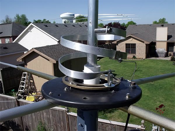
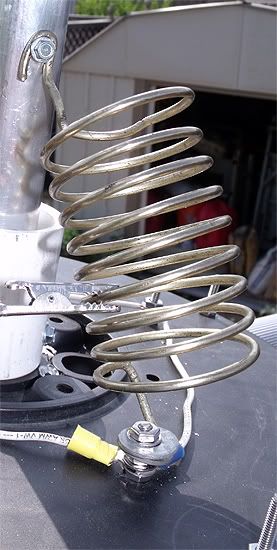
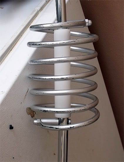
I have tried for a significant part of the day to get this antenna where it ought to be. No going there with the current matching system. A .64λ antenna length antenna should by nature be resonant lower than where I operate, so I am not surprised that the only good read from the 259B was on 26.125. SWR = 1.0 R = 50 X = 0 On 27.400 the best I got today after trying two different coils was with one of smaller coil diameter, and more wraps: SWR = 1.2 R = 48 x = 8 This was with a vertical length of 22' 10" as opposed to 23'. Some physical changes were done to improve integrity and appearance of the antenna. 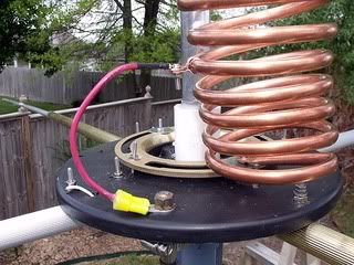 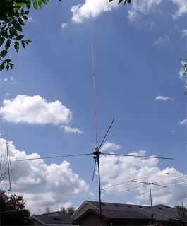 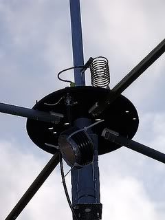 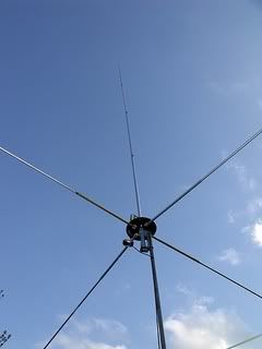 When you look at my photos there is no disputing that this is a homebrew. The brass floor flange is there to add strength to the spool end disc on which the GP radials are mounted, and to serve as the conductor between all the radials. When you look at my photos there is no disputing that this is a homebrew. The brass floor flange is there to add strength to the spool end disc on which the GP radials are mounted, and to serve as the conductor between all the radials. |
|
|
|
Post by cbrown on Apr 6, 2012 8:49:06 GMT -5
One suggestion: When you make the matching coil, try and get the spacing between each coil to be equal.
Also the length of the coil will affect the overall height of your antenna when tuning to specific frequencies.
|
|
|
|
Post by homerbb on Apr 6, 2012 15:58:35 GMT -5
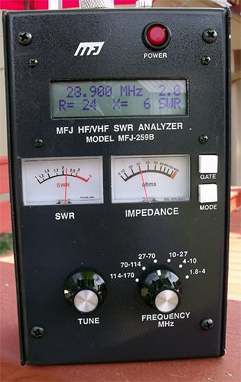
Thnx, cbrown. I'll keep those pointers in mind. I worked on this thing some more today trying to prove to myself it could be done. Here is what I did and the results. First using this coil:
2.0 R= 28 X= 21 --------- 28.713
1.5 R= 56 X= 21 --------- 28.108
1.2 R= 61 X= 7 ----------- 27.804 (lowest)
1.2 R= 53 X= 9 ----------- T5
1.2 R= 50 X= 11 ---------- 27.405
1.3 R= 52 X= 14 ---------- 27.185
1.5 R= 61 X= 22 ---------- 26.869
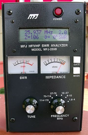
2.0 R= 110 X= 0 ---------- 26.244
Second using this coil:
2.0 R= 28 X= 20 ---------- 28.769
1.5 R= 53 X= 23 ---------- 23.243
1.1 R= 51 X= 5 ---------- 27.706 (lowest)
1.1 R= 52 X= 8 ---------- T5
1.2 R= 49 X= 10 ---------- 27.405
1.3 R= 51 X= 14 ---------- 27.185
1.5 R= 59 X= 22 ---------- 26.884
2.0 R= 110 X= 0 ---------- 26.249
Third using second coil and adding 10" to length to compensate for the portion of the vertical beneath the radials:
2.0 R= 27 X= 19 ---------- 28.814
1.5 R= 51 X= 23 ---------- 28.293
1.1 R= 60 X= 0 ---------- 27.754 (lowest)
1.1 R= 51 X= 6 ---------- T5
1.2 R= 48 X= 9 ---------- 27.405
1.3 R= 50 X= 13 ---------- 27.185
1.5 R= 59 X= 21 ---------- 26.859
2.0 R= 108 X= 0 ---------- 26.225
AT THE SHACK END OF THE FEEDLINE: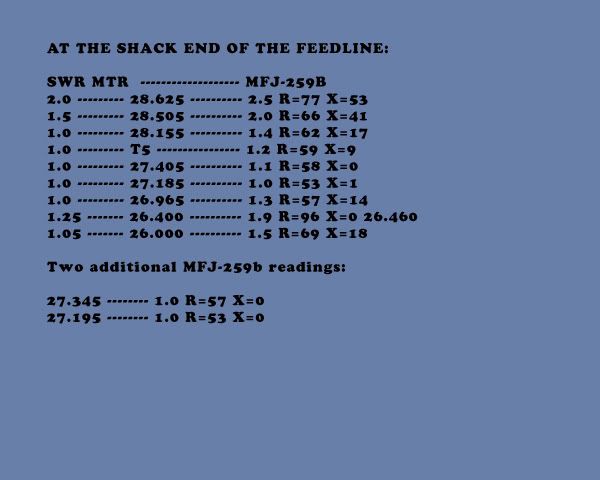 |
|
|
|
Post by homerbb on Apr 7, 2012 21:34:36 GMT -5
 Taking the readings from within the shack, antenna at 42' height: Taking the readings from within the shack, antenna at 42' height:
28.265 ------------ 2.0 R=61 X=34
27.979 ------------ 1.5 R=49 X=22
27.571 ------------ 1.0 R=45 X=1
27.555 ------------ 1.0 R=46 X=1
27.405 ------------ 1.2 R=49 X=9
27.185 ------------ 1.5 R=55 X=21
26.965 ------------ 1.8 R=74 X=27
26.549 ------------ 2.0 R=108 X=0It is much narrower banded, and friendly higher up the band. What the SWR meter in the shack says:
28.485 ------------ 2.0
28.305 ------------ 1.5
27.555 ------------ 1.0
27.405 ------------ 1.0
27.185 ------------ 1.05
26.965 ------------ 1.25
26.800 ------------ 1.45
26.600 ------------ 1.0
Seems the SWR meter has a different point of view on the whole thing. |
|
|
|
Post by homerbb on Apr 8, 2012 22:08:31 GMT -5
These readings are on the antenna after I brought it back down to 13' height so I can modify my tip over tower to make it more testing friendly.
What we have is several readings of the antenna with the latest matching system as previously posted. The readings are 4 different sets consisting of the
MFJ-259B connected to the antenna by e1/2λ x 6 coax, e1/2λ, 2' jumper, and directly mounted to the antenna feed point with a coupler connector.
This time around I found the analyzer behaved as it should directly against the bottom of the radials . . .
 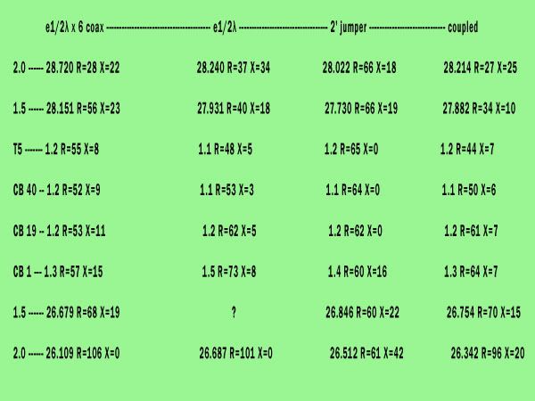 Apparently I failed to get a reading at the 1.5 bottom reading in the e1/2λ set,unless it was also 26.965 reading. Apparently I failed to get a reading at the 1.5 bottom reading in the e1/2λ set,unless it was also 26.965 reading.
|
|
|
|
Post by cbrown on Apr 9, 2012 8:44:47 GMT -5
When I use my MFJ, I use a tested piece of LMR400UF and my reading barely change from testing to mounting the antenna.
I like that antenna design, and the last coil you tested reminds me of Coily's design he uses.
Try moving the feed wire on the coil a little bit when testing at frequencies you want to use to get the resistive component of the impedance to where you want it.
|
|
|
|
Post by cbrown on Apr 9, 2012 8:45:24 GMT -5
Oh, and keep up the testing! That's the best part of the hobby!  |
|
|
|
Post by homerbb on Apr 9, 2012 10:28:47 GMT -5
Clearly here is some tightening up to do on it, but thankfully it's fun.
|
|
|
|
Post by cbrown on Apr 10, 2012 8:49:35 GMT -5
Clearly here is some tightening up to do on it, but thankfully it's fun. Ya, it is. When I was younger I did a lot of antenna design and theory, but as I got older I disliked going up on the roof as much as I did when I was younger. I'm glad to watch what you're doing. |
|
|
|
Post by homerbb on Apr 10, 2012 17:49:56 GMT -5
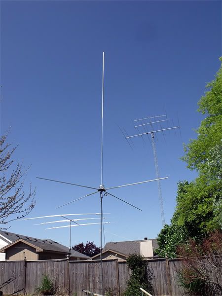
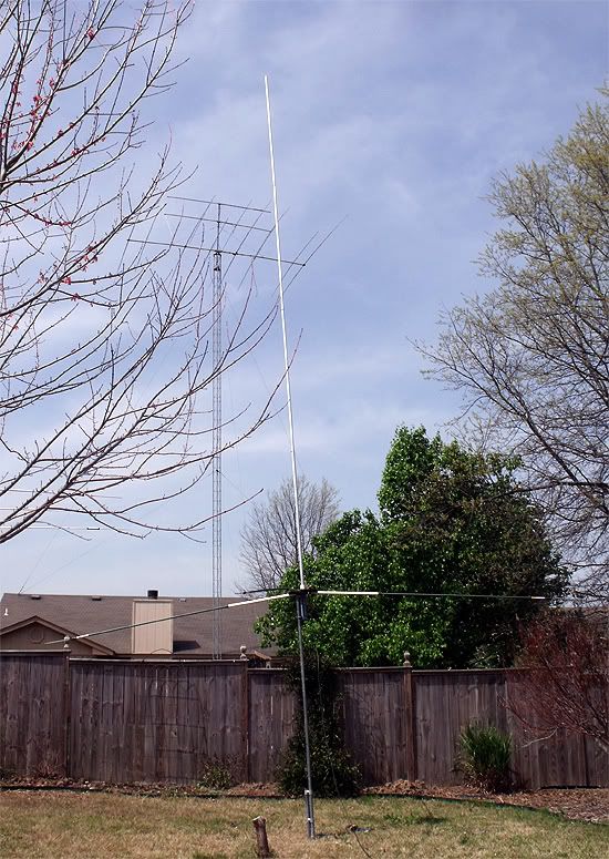
Well any pleasure it gives you adds to my own. I have made some modifications to the tip over tower that will beef it up. It is now comprised primarily of an ?- beam constructed of treated 2 x 10 x 16' and 2 x 4 marrying them together. Inside the beam I have mounted my 40' push-up so that the bottom of it is 1' above the break-over point. This allows me to extend the upper 30' of the pole when once I have the mast standing straight up. In the photo there is a 5' additional section of pipe between the top of the PU pole and the antenna which I will be removing in order to kee the antenna within reach when scoped in. i will be adding some ladder spikes in the top of the wooden portion of the mast to stand on so ads to have a better position for extending the PU pole rather than the top of my step ladder. I had to go to work so I didn't get it completed. Soon. BTW, it works quite well so far. In the photo the antenna sits at 23.5'. 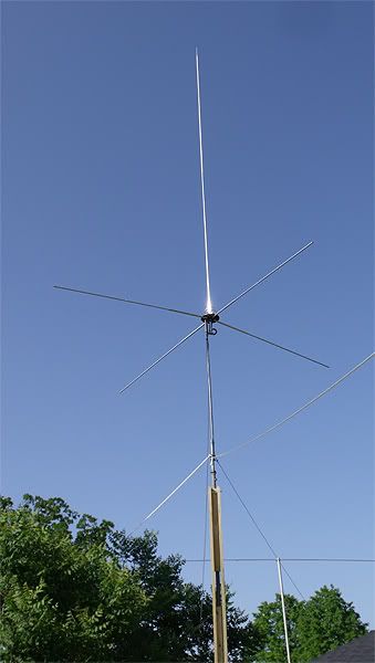 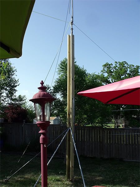 |
|
|
|
Post by cbrown on Apr 11, 2012 8:46:44 GMT -5
That's an interesting tip over tower design. I'm replacing my tip over tower, the one that was op was taken down for some house repair work and somehow got compromised by the construction workers. I'm not even sure the company is still in business.
Ah well, such is life. I strung up a nice dipole to at least keep me on the air.
|
|
|
|
Post by homerbb on Apr 11, 2012 12:57:22 GMT -5
I have a little more work to do on the tower to get it where I want it to be. One more innovation will be an 18" x 30" platform near the top of the wooden section that I can raise when I want to stand up there and work with the antennas, and will fold downward against the side of the tower when not in use. But so far I am adding a few more photos of the tower, and a link to a video of me lowering and raising it. Almost ready to get back to work on the antenna. 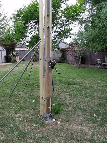 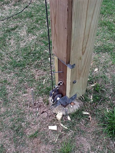 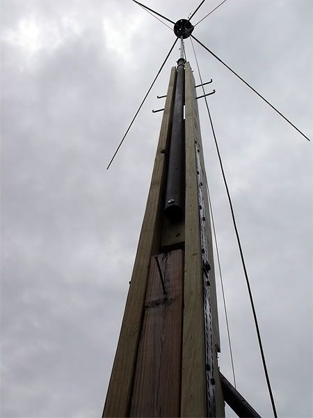 youtu.be/aTuYgahj2ek or cacirilo.multiply.com/video/item/24/TipOver01.wmv youtu.be/aTuYgahj2ek or cacirilo.multiply.com/video/item/24/TipOver01.wmv |
|


 .
.