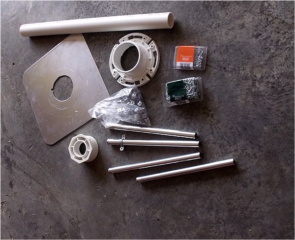
Parts list:
Four 10' fiberglass extendable fishing rods.
Four 1/2" x 12" aluminum (or your choice) tubes
Four 1/2" EMT pipe straps
Sufficient quantity of machine screws, nuts, and washers, etc.
One drywall hawk (or metal plate of your choice) 13" x 13" with center handle holder cut out
One toilet floor flange I chose the type that has internal 3" and external 4" diameters
One 3" x 1-1/2" PVC reducer bushing
One 1-1/2" x 24" PVC tube
Two 1/2" CPVC (hot water) sections of pipe
Four 3/8" x 4' fiberglass rods
At least 36.6' of wire - #16 stranded is what I used.
Two UV resistant 10" or longer cable ties.
Eight small 4" long UV resistant cable ties.
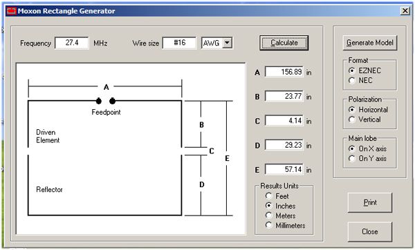
A free copy of the MoxGen program from online. Your wire size will determine the exact length of your elements. My
directions below are adjusted to the use of #16 stranded wire.
Instructions:
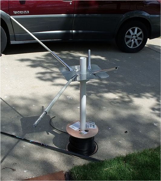
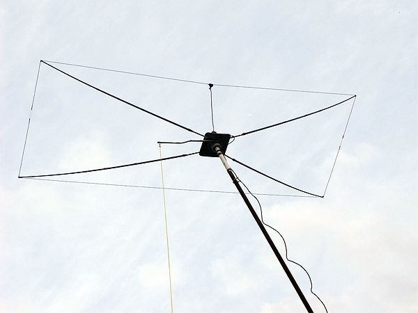
1. Using a drill bit to drill out a starter hole I then used a jig saw to remove the center of the drywall hawk to allow for the mast pipe to pass through the center of my spreader plate.
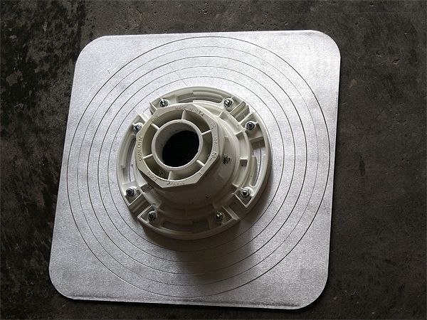
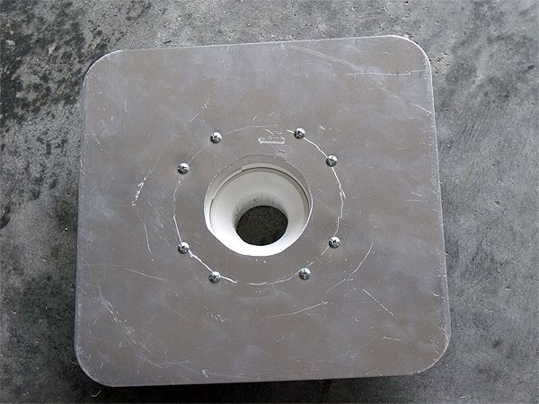
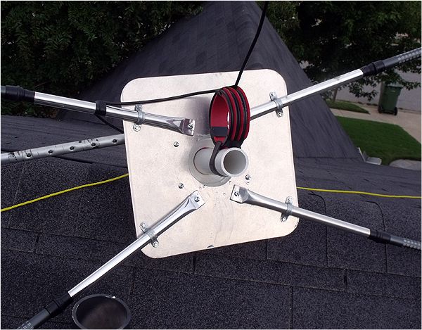
2. Aligned the toilet floor flange over the center of the aluminum plate and using a center punch I marked the holes for the machine screws that will hold the floor flange to the aluminum plate. Be sure that two of the flange screw holes on each side of the flange lip are aligned with the edges of the spreader plate. See the top of the spreader plate photo.
3. Drill out the marked holes and fasten the floor flange to the plate with machine screws and nuts(stainless Steel screws are the preferred type, but because this is not a radiating part of the antenna dissimilar materials are not of so much concern).
4. Next insert the 3" x 1-1/2" reducer bushing into the bottom of the floor flange. Based upon whether you are going to allow the mast pipe to run all the way through or simply mount the antenna on the top of the mast you decide whether to remove the stop lip one the inside of the bushing. Because I want to potentially use the Moxon beneath an Omni vertical antenna I removed the stop lip. either glue in the bushing with PVC cement, or use short screws to hold it in the floor flange.
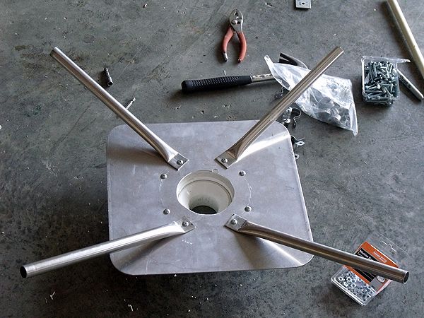
5. Flatten one end of the four 1/2" x 12" tubes up to 3/4" using a bench vice, or a hammer. Drill a hole in this flattened part of the antenna as seen in the photo of the top of the spreader plate. Four of the machine screws holding the flange on the plate are used to fasten the end of the tubes to the plate. Observing the top of the plate in my photo you can note that the four tubes are spaced widely apart on two opposite sides of the plate and more narrowly on the other two opposite sides of the plate.
6. Measuring about 5" up the four tubes from the flattened ends make a mark. At this mark measure toward the same edge of the plate 1-3/4". Two of the tubes will be fastened at this distance from that edge with one of the EMT straps on each of the two tubes. This is the side that I put the driven wire on. Follow the same procedure for the two tubes on the opposite side of the plate measuring 1" from the edge. Fasten these two tubes here. These two tubes are on the reflector wire side.
7. Measure 4' from the ends of the CPVC pipes and cut them resulting in four 4' long pieces. Insert each of the four 3/8" x 4' fiberglass rods into each of the four spreader tubes. These are for reinforcement of the poles. Placing the for CPVC tubes over each of these FB rods. This is for additional rigidity and reinforcement. I wrapped a few wraps of black vinyl electrical tape around the CPVC tubes right at the point where they exit the spreader tubes. This causes the fishing poles to fit more perfectly over these reinforcement rods/tubes.
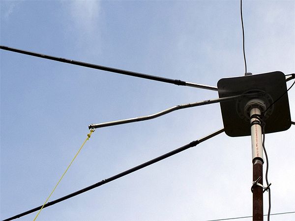
8. Slide the extended fishing poles over the CPVC pipes. I found that each of the tubes fit differently on the fishing pole because each of the poles had slightly differing internal diameters. I cut small amounts off the ends of the tubes as needed to allow the fishing poles to slide all the way up to the spreader tubes and over the vinyl tape . I then used black vinyl tape over the point where the fishing rods met the spreader tubes. Use the tape on the joints of the fishing rod extensions to prevent them some slipping back inside themselves.
9. Measure out from the center of the spreader plate center hole 83.5" and mark this point on the four fishing poles. On the two reflector poles move outward from these marks another 6" and cut these two poles at this point. On the two driver poles move out 3" longer and cut them here.
10. Using a file put a notch in the outer ends of all four poles.
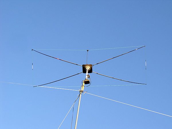
11. I used a 1-1/2" x 1/2" piece of PVC for a feed point insulator for the driven wire and two 1-1/2" x 8-32 SS machine screws with four flat washers and two nuts to make the connection points for the two halves of the driven wore and the coax feed line. Use whatever type of insulator here you wish, but limit the distance between the two driven wires to a small unspecified distance apart. Holes must be drilled through each end of the insulator for you SS screws to pass through and hold your wires and coax at the feed point of the antenna.
12. See the attached dimensions graphic for the length of the wires. This length is the sum total of the two parts of the wires folded back and the length across the wide side if the spreaders. For the two driven wires the lengths need to be at least four inches longer than exactly lengths required in order to turn them back into loops for the ends.
After the wire length for the driven element is determined and cut to length + 4", divide that wire into two exact pieces by folding it exactly in half and cutting it in the center of your fold. You now have the two halves of your driven element plus 2" each.
13. Strip one end of each driven wire and solder terminal eyelets onto them or turn them back and twist inot an eye and solder the twist for a good secure loop. Put this end under each of the SS machine screws heads between two of the washers on your insulator. Tighten this up on the opposite side of the insulator with one of the nuts on each of the screws. This will leave enough of the length of the SS machine screws onto which the remaining washers and two nuts will go. It is here you will attach your feed line.
14. Cut the remaining element according to the results from MoxGen, or the dimensions graphic I posted if using #16 stranded wire. This length must have at least 2" extra for folding back at its two ends and for adjusting for fine tuning if needed.
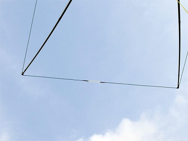
15. When these tow element wires - driven and reflector - are cut, folded back o themselves at the ends and secured with small cable ties use the two 10" cable ties to thread thru the end loops of each end of the wire elements. pull the cable ties through to slightly over 4" length when the cable tie is compressed flat. This is the insulators for the ends of the elements where they turn back toward each other.
16. Using a permanent marker measure back from the very ends of the loops on the wire elements the exact lengths required by the dimensions either generated by your MoxGen program, or on the graphic I posted. This is shorter for the driven wire and longer for the reflector wire.
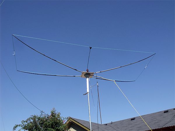
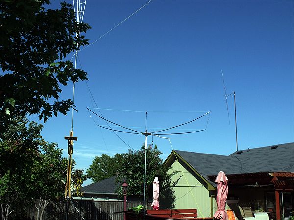
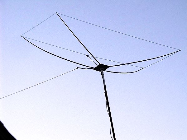
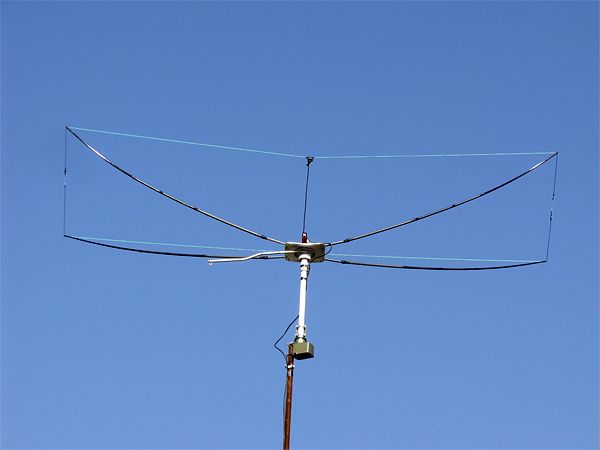
17. Now put your wires on the fiberglass fishing pole spreaders. Each of the marks you just made on the wire elements are where the notches on the ends of the spreaders will be placed on the wires. This will result in the pole spreaders being pulled into an upward arch providing the tension necessary to stretch the wire elements into useful radiating conductors.
If you used the reinforcements I suggested, or something of similar integrity, in side the first 4' of the fishing pole spreaders you'll have all the play you need in the spreaders without any concern for drooping. I used wraps of electrical tape at the ends of the spreaders to prevent the wires from slipping. When I have finished my fine tuning I will squeeze some silicone into the ends of each spreader and out and over the wires and pole ends to form a more permanent anchor for my wires to the spreaders.
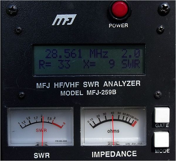
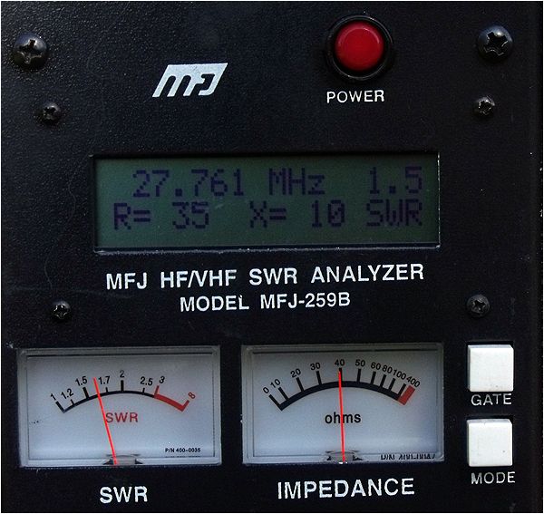
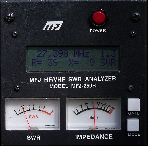
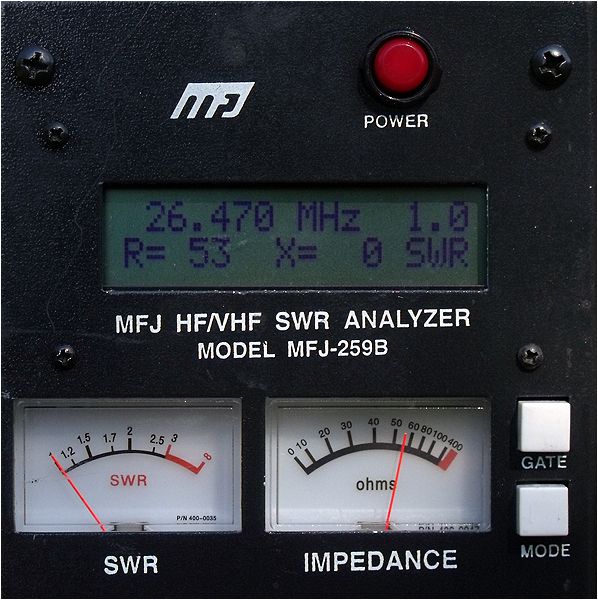
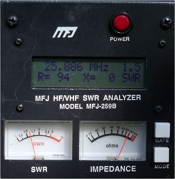
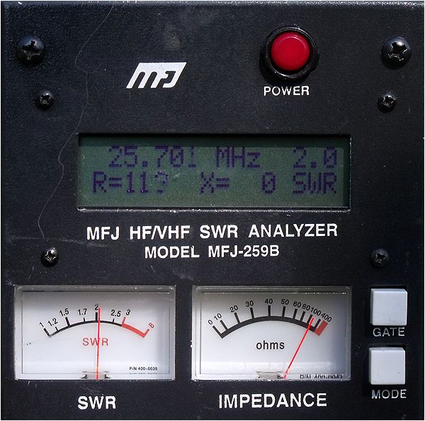
I have experienced the same I have read of others using the dimensions from MoxGen. The default tune for SWR and resonance lands lower on the band in the upper 26MHz range. Shortening of each of the element ends by evenly proportionate amounts should result in raising the resonant frequency.
Ask any questions to clarify anything that may be unclear to you.