


Converting the PAL VCO slider digital, for AM Brownings
Nov 28, 2016 0:22:09 GMT -5
tecnicoloco2000 and cbrown like this
Post by 2600 on Nov 28, 2016 0:22:09 GMT -5
Howdy, all! Here's a post from the CB Tricks forum, thought it might stir some interest here as well. Hven't gotten much farther than it shows here yet, ended up converting a couple of the PALs for 23-channel solid-state SSB radios. I'll post some of the how-to for that, later.
-- original post --
So, here's the preliminary start of a thread to cover conversion of PAL "VCO" 'slider' boxes from a 'wrong' frequency it was built with, to the one I want.
*** Disclaimer *** I'm not offering to sell any of the stuff needed to do this, especially *NOT* any of the crystals. Pretty sure we got the 22.1184 MHz crystals for this project from Digi-Key. About 15 years ago. Long enough that I can't remember what was the project they were meant for. Haven't checked to see if their stock number "X063-ND" is still valid.
Probably not.
The PAL was a cute design that achieved low drift by using a frequency optimized for stability in ALL the various frequency versions needed for dozens of different crystals it was meant to replace.
If you're not familiar with 23-channel radios, I'll just mention that adding more frequencies than it was legal to use was INCREDIBLY popular before the FCC allowed 40 CB channels. Since nearly every 23-channel radio used a collection of 12, 14, 20 or more crystals it was cumbersome to add more channels by adding more crystals. This worked, but the complexity got out of hand in a hurry, as well as the expense. The dollar price of a crystal was a lot lower back then, but a dollar was worth a LOT more.
A very few radios would give you a whole second 'set' of 23 channels by changing just two crystals. But most of the radios sold would only get you four new channels for each added crystal.
This made an external VFO look like an attractive solution. You would pluck one crystal out of the radio, hook up a shielded cable where the crystal had been, with the VFO on the other end of the cable. The drive signal from the VFO would usually 'fool' the 23-channel radio to run as if a crystal were installed in that slot. Since CB had a slang term for about everything back then, a VFO on your CB radio was called a "slider", for obvious reasons.
The Siltronix 80 and 90 VFOs were simply built with an oscillator circuit with a coil and capacitors that operated at the desired range of crystal frequencies. They were not terribly stable, but generally good enough for AM. Trouble was you couldn't make that design stable much above 20 MHz. The higher the frequency of a VFO, the more it will drift, as a general rule. This completely ruled out using a Siltronix with a 23-channel radio that used a 37.6 MHz crystal for channels 1 to 4. The drift factor at 23 MHz was bad enough, but at 37 MHz it would be too much even to operate AM, let alone sideband. Modifying a Siltronix to cover a different frequency range would totally nullify the dial markings. Each version had a different frequency pattern printed on the white plastic dial. Change the oscillator circuit, and the markings would NOT line up like before.
The PAL was different. The VFO operated at 5 MHz in all models. A crystal oscillator would feed into a mixer circuit, along with the 5 MHz VFO. Tuned circuits would select the desired sum of the two frequencies and feed that into the radio.
To modify a PAL to cover a different frequency range was not simple, and would require changing the crystal, as well as 10 or 12 coil, capacitor and resistor components.
But the dial would still read the same, since you had not changed the 5 MHz circuit that it's calibrated for.
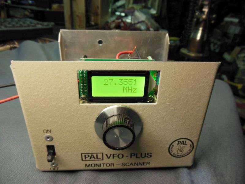
40 years later, this seems only a historical footnote, but what I'm going to present here is a totally different conversion project. We're installing a digital LCD frequency display and a keying circuit.
The reason for this is to use it with the older tube-type "un-convertible" 23-channel tube-type transmitters. The Browning 23S9, S23, Golden Eagle T68 and Mark II 69T transmitters all have one thing in common. The channel crystal operates on the same frequency that the receiver is listening to.
A slider that pumps this frequency into the transmitter will interfere with the signals coming down from the antenna. It will leak from the transmitter into the receiver. There is a button marked "SPOT" on these transmitter, that does this on purpose so you can line up the dial on your tuneable receiver with your transmit carrier. But you need to be able to turn this "Spot" carrier OFF.....
This will require installing a jack on the rear of the transmitter, to feed a switched voltage to the slider, and make it active only when you press the Spot or the PTT button on the mike.
So far, so good. I'll be using a batch of a half-dozen PAL VCOs that were built for a bunch of the 'wrong' frequencies. Wrong for this purpose, anyway.
The original "version 1" PAL manual posted at the main CB Tricks web site contains the specific component values to set one up for all the combinations that the factory would offer. This simplifies modifying the 'wrong' PAL for the radio you want to use it with.
www.cbtricks.com/miscellaneous/vco/pal/vco/graphics/pal_vco_1.pdf
BUT... The setup chart totally skips a 27 MHz output. Goes up to 23.5 MHz and then skips to 33 MHz. This will call for some 'cut-and-try' to get the component values right for a 27 MHz output.
Not rocket surgery, and we'll only have to do it once, and simply copy it for the remaining five of these in this batch.
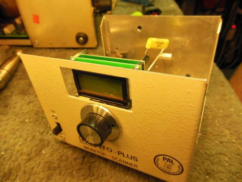
Assuming, of course, that we don't totally destroy any of them in the process. Just getting the counter's LCD display to mount behind the tuning-dial window uses up a fair part of a Dremel cutoff wheel.
The frequency display is a San-Jian type "PLJ-0802" widely sold on Ebay. Has a green backlight with black dot-matrix digits. It consumes only about 40 mA from a 8 or 9-Volt power supply. You don't want to feed more than about 9 Volts DC to it, or you risk overheating the built-in regulator chip.
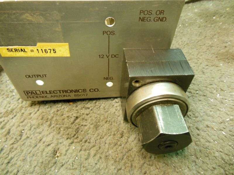
Safety becomes an issue any time you sell something with a 120-Volt AC power cord on it. The original 2-wire cord was legal in 1976, but we're installing a IEC socket that will accept any standard computer power cord.
The punch was not a cheap tool, but it has paid for itself compared to gouging out the hole the hard way.
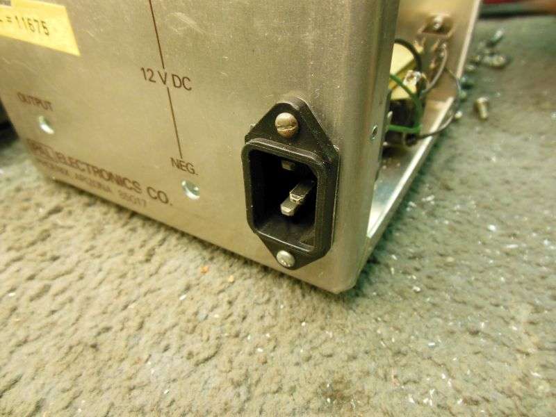
At least this way, you won't have any problem replacing the power cord if you lose the one that comes with it.
As you can see, this project is not terribly far along yet.
I'll post more as it develops.
---- (2nd post) ----
Just a quick note on this project. Made some progress.
Got the component values worked out, and it covers about 44 channels end-to-end. Not gonna be enough, but it's a start.
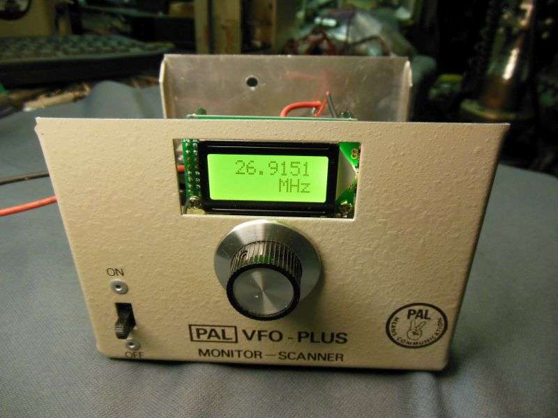
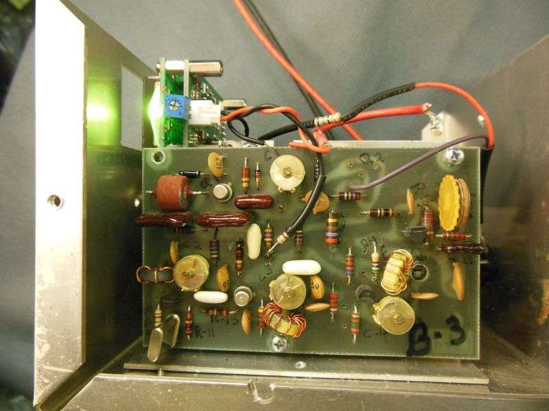
The blue trimpot against the side of the display was necessary to prevent the 5 MHz input from overdriving the counter input. Got some whacky readings at first. Feeding 5 MHz into a 500 MHz input can do this if the input level isn't in the sweet spot. The 68-ohm 1/2-Watt resistor flying above the pc board drops the output of the 12-Volt 7812T regulator down to 8.5 Volts. Since the counter's drain is constant, this works just fine without using a second 8-Volt regulator.
Still haven't installed the 'keying' circuit to shut it down in receive mode. And for now it's running from a current-limited bench supply rather than from 120 Volts AC. Much safer when dicking around inside the thing.
So far so good. Haven't blown up any hard-to-find parts yet.
Gotta decide where to put a "band" switch so it can cover more than just 44 channels. I hate to drill a hole in the front for a toggle switch, but that's how it's looking. Then again, I can make it more symmetrical by putting a small metal LED bezel on the opposite side, to indicate "keyed" status.
This project might actually turn out as intended.
Yay!
73
-- original post --
So, here's the preliminary start of a thread to cover conversion of PAL "VCO" 'slider' boxes from a 'wrong' frequency it was built with, to the one I want.
*** Disclaimer *** I'm not offering to sell any of the stuff needed to do this, especially *NOT* any of the crystals. Pretty sure we got the 22.1184 MHz crystals for this project from Digi-Key. About 15 years ago. Long enough that I can't remember what was the project they were meant for. Haven't checked to see if their stock number "X063-ND" is still valid.
Probably not.
The PAL was a cute design that achieved low drift by using a frequency optimized for stability in ALL the various frequency versions needed for dozens of different crystals it was meant to replace.
If you're not familiar with 23-channel radios, I'll just mention that adding more frequencies than it was legal to use was INCREDIBLY popular before the FCC allowed 40 CB channels. Since nearly every 23-channel radio used a collection of 12, 14, 20 or more crystals it was cumbersome to add more channels by adding more crystals. This worked, but the complexity got out of hand in a hurry, as well as the expense. The dollar price of a crystal was a lot lower back then, but a dollar was worth a LOT more.
A very few radios would give you a whole second 'set' of 23 channels by changing just two crystals. But most of the radios sold would only get you four new channels for each added crystal.
This made an external VFO look like an attractive solution. You would pluck one crystal out of the radio, hook up a shielded cable where the crystal had been, with the VFO on the other end of the cable. The drive signal from the VFO would usually 'fool' the 23-channel radio to run as if a crystal were installed in that slot. Since CB had a slang term for about everything back then, a VFO on your CB radio was called a "slider", for obvious reasons.
The Siltronix 80 and 90 VFOs were simply built with an oscillator circuit with a coil and capacitors that operated at the desired range of crystal frequencies. They were not terribly stable, but generally good enough for AM. Trouble was you couldn't make that design stable much above 20 MHz. The higher the frequency of a VFO, the more it will drift, as a general rule. This completely ruled out using a Siltronix with a 23-channel radio that used a 37.6 MHz crystal for channels 1 to 4. The drift factor at 23 MHz was bad enough, but at 37 MHz it would be too much even to operate AM, let alone sideband. Modifying a Siltronix to cover a different frequency range would totally nullify the dial markings. Each version had a different frequency pattern printed on the white plastic dial. Change the oscillator circuit, and the markings would NOT line up like before.
The PAL was different. The VFO operated at 5 MHz in all models. A crystal oscillator would feed into a mixer circuit, along with the 5 MHz VFO. Tuned circuits would select the desired sum of the two frequencies and feed that into the radio.
To modify a PAL to cover a different frequency range was not simple, and would require changing the crystal, as well as 10 or 12 coil, capacitor and resistor components.
But the dial would still read the same, since you had not changed the 5 MHz circuit that it's calibrated for.
40 years later, this seems only a historical footnote, but what I'm going to present here is a totally different conversion project. We're installing a digital LCD frequency display and a keying circuit.
The reason for this is to use it with the older tube-type "un-convertible" 23-channel tube-type transmitters. The Browning 23S9, S23, Golden Eagle T68 and Mark II 69T transmitters all have one thing in common. The channel crystal operates on the same frequency that the receiver is listening to.
A slider that pumps this frequency into the transmitter will interfere with the signals coming down from the antenna. It will leak from the transmitter into the receiver. There is a button marked "SPOT" on these transmitter, that does this on purpose so you can line up the dial on your tuneable receiver with your transmit carrier. But you need to be able to turn this "Spot" carrier OFF.....
This will require installing a jack on the rear of the transmitter, to feed a switched voltage to the slider, and make it active only when you press the Spot or the PTT button on the mike.
So far, so good. I'll be using a batch of a half-dozen PAL VCOs that were built for a bunch of the 'wrong' frequencies. Wrong for this purpose, anyway.
The original "version 1" PAL manual posted at the main CB Tricks web site contains the specific component values to set one up for all the combinations that the factory would offer. This simplifies modifying the 'wrong' PAL for the radio you want to use it with.
www.cbtricks.com/miscellaneous/vco/pal/vco/graphics/pal_vco_1.pdf
BUT... The setup chart totally skips a 27 MHz output. Goes up to 23.5 MHz and then skips to 33 MHz. This will call for some 'cut-and-try' to get the component values right for a 27 MHz output.
Not rocket surgery, and we'll only have to do it once, and simply copy it for the remaining five of these in this batch.
Assuming, of course, that we don't totally destroy any of them in the process. Just getting the counter's LCD display to mount behind the tuning-dial window uses up a fair part of a Dremel cutoff wheel.
The frequency display is a San-Jian type "PLJ-0802" widely sold on Ebay. Has a green backlight with black dot-matrix digits. It consumes only about 40 mA from a 8 or 9-Volt power supply. You don't want to feed more than about 9 Volts DC to it, or you risk overheating the built-in regulator chip.
Safety becomes an issue any time you sell something with a 120-Volt AC power cord on it. The original 2-wire cord was legal in 1976, but we're installing a IEC socket that will accept any standard computer power cord.
The punch was not a cheap tool, but it has paid for itself compared to gouging out the hole the hard way.
At least this way, you won't have any problem replacing the power cord if you lose the one that comes with it.
As you can see, this project is not terribly far along yet.
I'll post more as it develops.
---- (2nd post) ----
Just a quick note on this project. Made some progress.
Got the component values worked out, and it covers about 44 channels end-to-end. Not gonna be enough, but it's a start.
The blue trimpot against the side of the display was necessary to prevent the 5 MHz input from overdriving the counter input. Got some whacky readings at first. Feeding 5 MHz into a 500 MHz input can do this if the input level isn't in the sweet spot. The 68-ohm 1/2-Watt resistor flying above the pc board drops the output of the 12-Volt 7812T regulator down to 8.5 Volts. Since the counter's drain is constant, this works just fine without using a second 8-Volt regulator.
Still haven't installed the 'keying' circuit to shut it down in receive mode. And for now it's running from a current-limited bench supply rather than from 120 Volts AC. Much safer when dicking around inside the thing.
So far so good. Haven't blown up any hard-to-find parts yet.
Gotta decide where to put a "band" switch so it can cover more than just 44 channels. I hate to drill a hole in the front for a toggle switch, but that's how it's looking. Then again, I can make it more symmetrical by putting a small metal LED bezel on the opposite side, to indicate "keyed" status.
This project might actually turn out as intended.
Yay!
73


