|
|
Post by cityslicker on Mar 8, 2019 15:34:02 GMT -5
I had seen this in complete detail a few years back online no that i need it cant find it anywhere does anyone have this in detail Thank you
73's
|
|
|
|
Post by BBB on Mar 9, 2019 10:03:10 GMT -5
For $1895.00 you to can own this Super Wack Packed Yellow Washer Machine Co. modified for AM only browning Mark III Transmitter. Our own retired browning engineers have exclusively removed the USB and LSB markings from the faceplate plate of the radio giving you the loudest, cleanest, most far reaching AM only performance ever achieved from a single Mark III transmitter. You have got to have this! Use your Mom's trust fund to buy this to impress your friends!  NOTE: Actual performance may differ as a result of end-user environment and application. All values are design or typical values, measured under laboratory conditions at 25 °C. Specifications subject to change without notice. |
|
|
|
Post by SIX-SHOOTER on Mar 9, 2019 11:35:51 GMT -5
Well even if you remove the SSB the two transmitters are different sizes so it won't look like a regular AM only transmitter.I don't have that issue since SSB has never worked on my MK III transmitter & I never use it anyway.It just sits on the shelf & collects dust since I have many other radios that I much prefer.I have owned three or four MK III SSB transceivers & none were impressive in my opinion.I much prefer my MK IVA, DAK X, & D201A overall & several others just for AM.
SIX-SHOOTER
|
|
|
|
Post by cityslicker on Mar 13, 2019 11:58:26 GMT -5
The reason I am asking for this process is because i have read a lot of places that it is better to bypass the ssb switch when it goes my switch arcs when you key the mic so i was just going to bypass the switch. was just looking for a little help with the process. its not the older version this one has the cb/hf/xtl switch on the receiver
|
|
|
|
Post by 2600 on Mar 13, 2019 17:23:43 GMT -5
Umm, it's not so much which receiver you have, it's which transmitter. There are two basic versions of the transmitter. The original one that has no ALC adjustment is wired a bit differently from the later version, revised in either 1973 or 1974 IIRC. It has a trimmer pot with a very-short quarter-inch shaft with a screwdriver slot, poking up on the chassis deck between the driver and final tubes, and the outside edge of the chassis. I have used a text file that we worked up here. One version of the file for the pre-ALC transmitter, one for the later transmitter. Had the notion of writing it up with pictures as a "how-to", but it never got far past that, for use by techs here. As it turns out, the detailed description with the wire colors to take loose and move also has problems. Browning would change wire colors from one production run to the next. Pictures help keep this from being a problem, but putting them all together just sorta simmers on a back burner. When a customer's transmitter gets "hot-wired" for AM only, errors or changes in wire colors sometimes get updated to that file. Sometimes not. More than once a customer who seeks to resell a radio will want only the circuits that have broken down on the selector to get bypassed, skipping the ones that have not gone bad. Saves him some labor cost. That's a big deal for a horse-trader who wants to minimize his cost to get the thing sold. First hint that the mode selector has failed and shorted between separate circuits is a burned R51, like this: 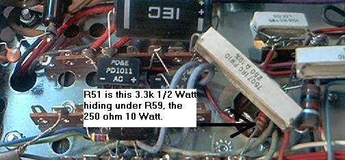 This kills all mike audio when it gets fried. The next-most aggravating failure is the circuit that selects the input for the "Mod" feature on the meter-function selector. Puts a few hundred Volts on the meter. Pegs it out on receive. Don't even have to key the mike. Eventually it burns out the coil in the meter. No way to fix that, but a new meter. But yeah, this is a project that just keeps on not-quite happening. Maybe after the tax-refund season dies down? Maybe? 73 |
|
|
|
Post by cityslicker on Mar 13, 2019 18:27:02 GMT -5
Thank you for your reply. Turned it on one day went to transmit the switch arced turned it off unplugged it hasnt been powered on since. I will pull the cover off to check the trimmer pot inside. to find out which version it is
|
|
|
|
Post by cityslicker on Mar 15, 2019 10:21:58 GMT -5
ok i do have the trimmer pot near the final marked t4 . turned the transmitter on. and the meter is not pegged in mod mode. the lights for am lsb usb are not on did not key it
|
|
|
|
Post by 2600 on Mar 15, 2019 22:54:18 GMT -5
The three mode-indicator lights are powered by the regulated 150 Volt DC supply.
Good chance that the 150-Volt 10-Watt zener diode is shorted. When this happens, R60, the enormous 8.5k power resistor that feeds it will now get REALLY hot. A short between circuits on the mode selector can overload the zener and cause it to fail as a short circuit. A new zener won't last long if a short on the mode selector caused it to fail the first time.
A check with the ohms function of a typical multimeter, with the black probe grounded and the red probe to the terminal on the zener will show a short if the zener got slammed. Checking R60 would be a good thing to do if the zener checks shorted. It will fail if it runs that hot for too long.
73
|
|
|
|
Post by cityslicker on Mar 21, 2019 9:59:51 GMT -5
Ok i replaced R60 R61 and vr 1 Didn't check them with a meter just went ahead and replaced them not going to power on the radio until i bypass the switch
|
|
|
|
Post by cityslicker on Mar 27, 2019 13:28:59 GMT -5
Replaced the switch and transmitter is working great thank you for your help... now a new problem when i switch over to the siltronix model 90-3 everyone says i have a hum on transmit thought maybe it was the cable from the transmitter but it wasnt i replaced it with a heaver video cable and still hum anyone have any ideas?
|
|
|
|
Post by 2600 on Mar 28, 2019 21:41:51 GMT -5
There are two filter capacitors in the Siltronix VFO. Good chance that one or both of them is no longer working right. The large one is 1000 uf and the smaller one is 220uf. I recommend using new parts with twice the old capacitance rating. A 2000 or 2200uf for the large one and a 1000 uf part for the smaller one. Voltage rating should be 25 Volts. Higher is okay.
Might be the whole problem, might not. But those two electrolytic capacitors are both past their "use-by" date just the same.
One good way to confirm this calls for a shortwave or ham receiver that can tune in the 16 MHz drive signal from the VFO. If you can tune in the carrier coming out of the VFO, you will hear a hum on the carrier if the VFO's filter caps are really bad. If your receiver can select FM also, the hum will be louder than it is when listening in AM mode, if I'm right.
73
|
|


