|
|
Post by wildcat444 on Jul 16, 2021 14:35:28 GMT -5
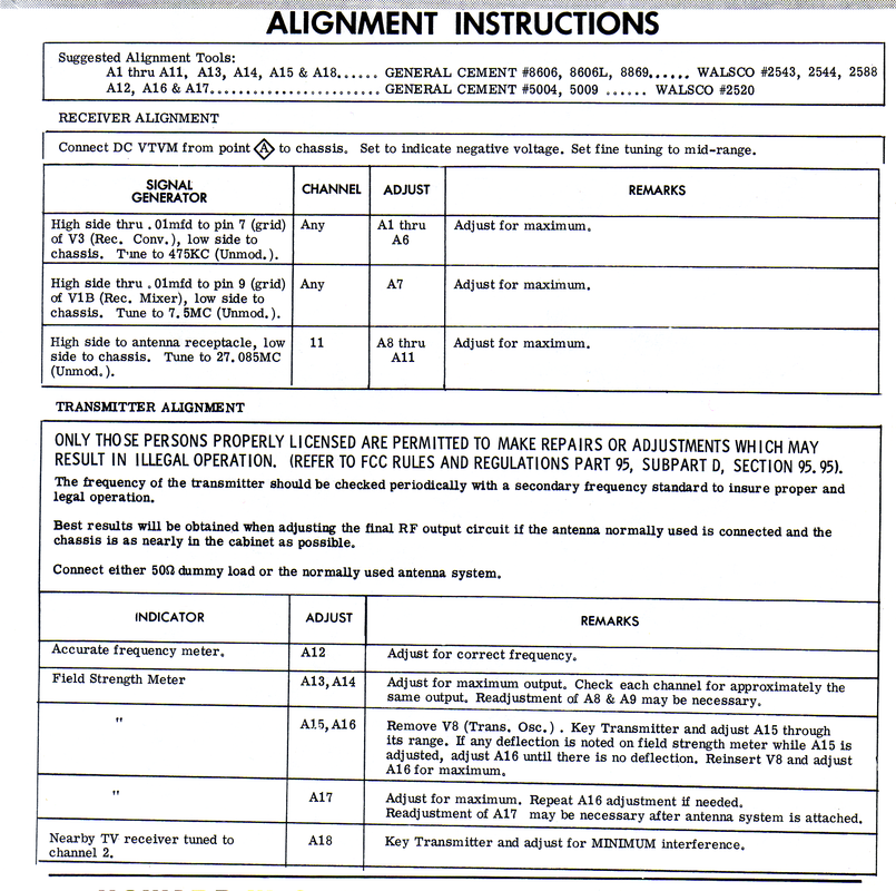
Hello, I have a Cobra CAM 88 which is a simple 23 ch AM tube radio with equally simple alignment instructions. This alignment seem perfect for a first time attempt. There are really only a few steps each for the RX and the TX on this radio. I just recaped it after not using it for nearly 30 years and it appears to be RX & TX as it did when I last used it in the early 90s. I hope I have the necessary equipment to do at least a moderate alignment, but need some advice/assistance on how. The second half (for the TX) seem pretty strait forward, but the Receive alignment is what I am not sure about. For RX, it looks like I'm just injecting signal at a pin of a tube, then another tube, then the antenna jack and making my adjustments along the way. But what signal?
I have a B&K 2040 Cb Signal Generator. I read that the 475KC first called for here isn't really a standard used on most CBs, and the only way I see to change the frequency is the regular 40 channel dial on the generator. 27Mhz is far from 475KC. I am guessing this means I can't dial up 475KC with the B&K 2040 (or 7.5MC)?
I also have a frequ. counter, scope (though I'm not fluent using it), Bird watt meter, dummy load, B&K 1040 Service Master. Admittedly, I don't have any experience with the BK CB servicemaster/Sig Gen., but I do have a fair amount of basic electronics knowledge and I am great with direction. Any guidance on doing this?
 |
|
Sandbagger
Administrator/The Boss 
Posts: 6,250 
|
Post by Sandbagger on Jul 17, 2021 22:20:03 GMT -5
Hello, I have a Cobra CAM 88 which is a simple 23 ch AM tube radio with equally simple alignment instructions. This alignment seem perfect for a first time attempt. There are really only a few steps each for the RX and the TX on this radio. I just recaped it after not using it for nearly 30 years and it appears to be RX & TX as it did when I last used it in the early 90s. I hope I have the necessary equipment to do at least a moderate alignment, but need some advice/assistance on how. The second half (for the TX) seem pretty strait forward, but the Receive alignment is what I am not sure about. For RX, it looks like I'm just injecting signal at a pin of a tube, then another tube, then the antenna jack and making my adjustments along the way. But what signal?
I have a B&K 2040 Cb Signal Generator. I read that the 475KC first called for here isn't really a standard used on most CBs, and the only way I see to change the frequency is the regular 40 channel dial on the generator. 27Mhz is far from 475KC. I am guessing this means I can't dial up 475KC with the B&K 2040 (or 7.5MC)? I also have a frequ. counter, scope (though I'm not fluent using it), Bird watt meter, dummy load, B&K 1040 Service Master. Admittedly, I don't have any experience with the BK CB servicemaster/Sig Gen., but I do have a fair amount of basic electronics knowledge and I am great with direction. Any guidance on doing this?
475 Khz is the IF frequency of the radio. You need a signal generator that can tune to that frequency in order to inject that signal. However, if you don't have one of those, you can still align the radio sufficiently enough by just putting in the on-channel output of the B&K 2040 into the antenna jack and simply peaking all of the coils for max signal while reducing the signal level to keep the s meter around s3 so as not to hit the receiver AGC as you align the coils. It is helpful when aligning the IF cans, to put a scope on the audio output (detector output would be better) and with a 90% modulated input signal, make sure that the output sinewave on the scope is symmetrical and clean on both peaks. If the coils are misaligned the sinewave will distort and result in "rough" sounding audio when receiving. I should also mention that you should make sure that all of your crystal frequencies are correct before starting the alignment. A crystal that is off, will cause your alignment to be off as well. |
|
|
|
Post by wildcat444 on Jul 18, 2021 8:27:09 GMT -5
Wow, thank you for the reply. Since this is my first time, I will try using the 2040 as you suggested. Can you elaborate on what you mean by your suggestion to make sure that all of the crystal frequencies are correct before starting the alignment? It appears that there is only one adjustment for the frequency alignment, which according to the schematic, seems to indicate is for overall frequency alignment. I don't think I have much choice to do anything other than that frequency alignment (which is called for down in the TX section).
|
|
Sandbagger
Administrator/The Boss
Posts: 6,250
|
Post by Sandbagger on Jul 18, 2021 14:52:27 GMT -5
Wow, thank you for the reply. Since this is my first time, I will try using the 2040 as you suggested. Can you elaborate on what you mean by your suggestion to make sure that all of the crystal frequencies are correct before starting the alignment? It appears that there is only one adjustment for the frequency alignment, which according to the schematic, seems to indicate is for overall frequency alignment. I don't think I have much choice to do anything other than that frequency alignment (which is called for down in the TX section). Most AM only radios don't have adjustments on each individual crystal. Which is a shame because crystals do drift with age, sometimes drastically. So even though you can't adjust the frequencies of each individual synthesizer crystal, you should measure them with the frequency counter to make sure they aren't way out of tolerance. You will not be able to properly adjust the receiver if the crystals are way off. |
|
|
|
Post by wildcat444 on Jul 18, 2021 18:57:42 GMT -5
Alright, thank you. You also mentioned that it is helpful when aligning the IF cans, to put a scope on the audio output (detector output would be better) with a 90% modulated input signal to make sure that the output sinewave on the scope is symmetrical and clean on both peaks. What is the detector output on this radio? I was looking at the schematic below, but wasn't sure...  |
|
Sandbagger
Administrator/The Boss
Posts: 6,250
|
Post by Sandbagger on Jul 20, 2021 21:00:59 GMT -5
Alright, thank you. You also mentioned that it is helpful when aligning the IF cans, to put a scope on the audio output (detector output would be better) with a 90% modulated input signal to make sure that the output sinewave on the scope is symmetrical and clean on both peaks. What is the detector output on this radio? I was looking at the schematic below, but wasn't sure... The easiest place to pick up the detector output is on the high side of the volume control. When checking audio symmetry, you may have to increase signal generator output enough to remove the noise that will accompany the audio signal. Tune the IF (only!) cans for the cleanest and largest amplitude sinewave. The earlier receiver coils, before the IF can be tuned using the s-meter to peak with minimum signal level, and only 30% modulation is needed there. |
|


