|
|
Post by twister526 on Oct 5, 2009 21:20:17 GMT -5
Have an Mark III. Loud humm on transmitt, sounds like your talking into the back side of an fan when modulating. Have checked tubes, and capacitors, resistors. Came with Siltronix VFO model 90, rca cable wired into crystal socket, dosent seem to work, could something in the mods for the VFO be causing the hum?
|
|
|
|
Post by 2600 on Oct 6, 2009 23:29:18 GMT -5
So, I gotta ask. How did you "check" 35 to 40 year-old electrolytic capacitors to see if they are good?
Or how many of them? If what you mean is a visual inspection only, that's really not a "check", like an electrical test. If they "look" good, this has no meaning at all in the real world.
I'm serious. Mostly I skip checking them in a radio this old. If the electrolytic filter caps in the power supply are still good, this is an honest-to-goodness accident. Every, single last one of them SHOULD be bad by now. If they are all good, either this is a genuine miracle, or the radio was unpacked from the factory box by you, with under 500 original miles on it.
I will make some predictions.
The radio has a fairly high "mileage".
At least one-third of the tubes will flunk on a proper tube tester.
At least two out of three electrolytic caps will flunk an electrical test.
The AM/LSB/USB mode-selector switch will show signs of scorching around the rivets that hold the fixed contact points to the insulating ring.
The relay will prove to be worn and unreliable once all this other stuff gets fixed properly. You can no longer buy this relay new, so replacing it requires that you also replace the socket, as well.
Cleaning the controls, switches and relay contacts is usually a good idea just to start. If the Mode selector switch has two pieces of bright blue plastic in the hub where the shaft turns the contacts, use nothing meaner than denatured alcohol to clean it. Every, single other solvent that is legal to sell this century will dissolve this blue-plastic hub and destroy the switch, even if it's like new. In 1976 it was still legal to use a freon-based cleaning solvent. Wouldn't harm that kind of plastic. Can't buy that contact cleaner now. Not all Mark III transmitters used that exact mode switch. Be extra careful when you see that BLUE in one of these.
Seriously, would you hop into a 1970 or 1976 car and take off for a 1000-mile roadtrip because everything it "Mint"?
Wouldn't get far. Not until hundreds of seals, gaskets, hoses, bushings and other rubber parts get removed and replaced. A 1970 or 1976 radio will have maintenance issues from age alone, even if the odometer hasn't turned past the first thousand miles.
73
|
|
|
|
Post by BionicChicken on Oct 7, 2009 12:05:30 GMT -5
The "talking through a fan" comment would lead me to think either a tube with a grid short, a leaky cap, or a bad diode. On the VFO just switch to a crystal controlled channel to see if that clears it...........I doubt it however. I'm sure you checked the tubes for grid leakage and shorts...........a tube with these problems can still show good emission.
The way I look at it is you wouldn't rebuild the motor of an automobile if all that was wrong was the brakes needed replacing. If it drives and operates like it should that ought to be enough. But that is just my opinion and might not be the way you want to go.
Hope you can get it going. There is nothing more rewarding than fixing a radio yourself and then talking on it.
|
|
|
|
Post by twister526 on Oct 7, 2009 17:08:57 GMT -5
I have posted before, and gotten alot of good helpful info and I greatly appreciate it. I realize constructive critisisim is a good thing, and I always try to take the good from everything and everyone and over look the bad. I feel like I do that quite well and did with my past post. But I go to tell you even I will overlook so much, I am an 40 year old adult, a man an faily intelligant man, with alot of expirence working on radio equipment, and I am quite capable of keeping my radios and most of the radios in the local are going as a hobbie not an business, and its an hobbie I enjoy or I wouldnt do it. What I dont need is preached at unnecessisarily. I post these questions for one to take a part in a great forum, and two there are alot of you a lot more knowledgable on the tube stuff and browning than myself. But I know commen sense when it comes to repairing a radio. when I say I checked the caps. That means I replaced the 45 year old caps, but I am quite capable of testing them if I feel I need to. Just becuse I post questions dosent meen Im an idiot on the subject, just meens I may be looking for smarter opinions, and ideas. Then if I decide it needs an complete rebuild then I will be the one to do it, and I may need to ask  a few more quesions along the way. Just trying to enjoy the forum and all the good people on it. Thanks to all! Twister526 |
|
|
|
Post by rjordan on Oct 7, 2009 18:03:57 GMT -5
I pulled out my schematic on this sweet old bird and looked it over for some suggestions to pass along. I'm a big fan of the old "divide and conquer" method of troubleshooting, so my thoughts are long those lines.
Not being to hear the radio makes me want to track down the source of the hum.
I'd try to break out the audio section from the RF section, and if that fails, then I'm probably looking at a power supply problem.
First of all, I'd try to figure out if it was 60Hz or 120Hz hum I was hearing. 120Hz is indicative of a power supply situation. 60Hz hum points towards a ground loop, open ground, or tube issue with a heater element.
1. Turn R38 all the way CCW, thus eliminating the first two audio stages, and see if you still have the hum. if so..
2. With the radio turned off, I'd pull the 6BQ5 modulator, then restore power and see if the hum was still present. Given the potential for spikes resulting from removing and re-inserting the tube with the radio hot (Lenz's law at work), I try to always remove power whenever removing or re-installing the modulator tube. Hum still there?
3. From the sounds of things, I'd say you probably have a scope. Take a look at both sides of R59 (I'm working from a Sams, but just double checked the schematic on-line at cbtricks and it's the same). R59 is the smoothing resistor between C62 and C61b.. It's the 250 ohm 10 watt resistor. That's the main B+ feed, and I like to see no more than 5% peak to peak ripple to B+ ratio... , but let's say 10% so 40 volts peak to peak on the output side of R59. Checking the input side of R59 at least gives you an indication that you don't have a gross problem on the input side of the filter. You'll want to have the TX keyed while looking at the ripple. Easiest to AC couple for this measurement. The main B+ (380V) is a half wave doubler, so it will have more ripple than a normal full wave/bridge type rectifier
If all's good there, check the ripple on the - 45 volt supply. You can grab that at the "high" side of the bias pot. Maybe I should say the ungrounded side of the pot since "high" here is really "low" relative to ground ;D
While you're at it, take a look at the voltage on the stud mounted zener regulator VR1 - should be around 150 volts +/- 10%
4. If you still have the hum with the 6BQ5 test, and the power supply ripple looks good, I'd suspect a leakage path between the heater and cathode on one of the tubes in the RF path. Easiest and most exact way to check for this is just sub a known good tube in it's place. Hopefully you have some spares to cover that. I can tell you I've seen a lot of 6GH8's develop a leakage path between the heater and cathode. This tube was a big fixture in many older TV sets, and I even came across an old reference in the late Jack Darr's service clinics about this problem and this tube as I recall.
Sorry for the misspellings, etc... I'm trying to get out the door and get dinner. Good luck and keep us up to date!
Rick
|
|
|
|
Post by 2600 on Oct 8, 2009 0:43:32 GMT -5
Hmm. A response that is "complete" enough to be useful to a newbie will insult the intelligence of someone with practical experience.
As a rule, anyone who will reveal a little detail up front, like
Please, feel free to spend a few words to point this out up front, before I waste a pile of words.
If in fact you were a Browning 'newbie', that level of detail would have some value. And I will not waste any words griping about how easily someone could have saved me a pile of unnecessary typing.
I make an effort to maintain a constructive, practical and respectful tone. I apologize for appearing to "talk down". A small hint that you have already climbed the ladder is valuable here. And for a fella sitting at the base of the ladder looking up, the view is different.
A 'scope is the veritable "Swiss Army Knife" for a problem like this. Do you have access to one?
Narrowing this down to either the audio chain V7-8-9, or to the carrier chain would be my next suggestion.
If you pull out V9 and key the mike, does the hum go away in the transmitter's carrier?
If not this points away from the three audio tubes.
73
|
|
|
|
Post by 2600 on Oct 8, 2009 1:14:58 GMT -5
Ooh. Just caught one detail from the original post I had missed. "rca cable wired into crystal socket". Oops. Not the right way. May not be the root of the main problem, but a problem in the making. The crystal socket is NOT the place to wire the cable in this transmitter. The cable shield must go to ground. And there is NO ground connection on the crystal socket. We lap-solder a wire onto the shield, and run it into the grommet below the crystal selector, alongside the yellow wire from the selector to V6. There is a ground lug very near the grommet under the deck. The center wire should get soldered to the switch lug, not the crystal socket. Like this: 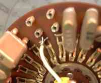 Missed that first glance. 73 |
|


 a few more quesions along the way. Just trying to enjoy the forum and all the good people on it. Thanks to all! Twister526