|
|
Post by northernlights on Feb 7, 2011 20:44:27 GMT -5
HI all, This is my 1st post here as I'm new, and I have a question about CB radio antenna grounding that perplexes me. I've got an old Realistic Navajo base station that seems to work ok, as it's one of the newer models in black plastic, a TRC-433 (not the old wood grain ones), and I've also got a Cobra mobile CB radio, model 18 WX ST II, and all I have for now is a crappy magnet mount helical wound stubbie antenna that is about 18" tall or so (haven't measured it, not sure, sorry) that is connected via about 100 feet of Amphenol RG213/U cable. I also have a new Realistic brand SWR Power meter Field strength meter that is connected between the heavy cable that the antenna is connected to, and the CB radio. I previously had the "stock" piece of cable connected to this antenna when it was mounted on the roof to my minivan, but over the period of about a year or so, the magnetic mount totally rusted away, so I removed the antenna via the one ground bolt it was attached to the mount with, and then mounted it to a piece of aluminum plate about 10" square. I then mounted this aluminum plate to the side of my house via an "L" bracket. I then cut off the stock cable from the antenna, and connected the RG213/U cable to it to replace the stock cable, as the stock cable was frayed from being slammed in a door too many times, and needed to be replaced anyhow. I "thought" I would be able to easily just solder on the new antenna to the RG-213/U cable and all would be good, but oddly enough, I noticed something "weird" when I transmit now that the new large cable is connected to the rig. When I key up when I have the Navajo base station TRC-433 connected to the SWR/power meter, and thus the antenna via the RG-213/U cable, and it is on channel 1, I notice that I now ONLY have about 4 bars showing on the TX LED meter of the base station, where before it pinned the meter every time, but more alarmingly, the higher the channel, the LESS power output there seems to be, until you get up to channel 40, where there is ONLY ONE bar of power showing. Now here's the REALLY weird thing, when I disconnect my TRC-433 from the antenna and power meter, and connect the Cobra mobile one, (which is powered via a 12V car battery if that matters at all) in it's place, the EXACT OPPOSITE applies, meaning that the same power loss is observed, only in REVERSE, channel 1 has only ONE bar of power showing on the CB LED bar graph for the power, and channel 40 has FOUR bars showing, which is indicating that more power is being transmitted on channel 40 than on channel 1. This confuses me! I checked and double checked that there was no shorts between the core conductor of the cable and the outer braided copper grounding wires, and also that where the antenna was soldered to the RG-213/U cable that it was done properly, with no cold solder joints or anything shorted anywhere. The SWR meter shows that there is no SWR happening at all either, so it's not like there is some kind of power loss due to that, and the meter seems to be working fine. It's something to do with that antenna, and the grounding I think, but I just cannot put my finger on it. Since an antenna like that relies on the roof of the vehicle for a ground plane, I'm aware that one must ground the antenna wire ground, as well as connect a ground plane, which I have done in the form of 4 pieces of 14 gauge copper wire cut to 105" lengths attached at the antenna where the ground of the cable is connected to it, and nothing is shorted either. I also have a 5th piece of the same wire, also attached to the ground terminal of that antenna, which leads to a piece of long copper pipe that I hammered into the ground, which is quite wet right now, as there is about 2 feet of snow on the ground here in Nova Scotia presently! So what am I missing, or doing wrong? Another weird thing was that BEFORE I added the ground plane wires and the ground pole connection to the antenna to ground it all to the ground, I had the weather channel on the Cobra CB playing, so i could hear the effects of the grounding wires as i attached them, thinking it would show an improvement, but it actually made the reception WORSE, it was more staticky and fuzzy after I added the ground plane wires and grounded them all to the pole driven in the ground. Shouldn't it have made it all BETTER?? I also noticed that BEFORE I added the grounding pole in the ground connection, the same issue existed with the power decrease, but not as much, before I connected the antenna ground to the grounding pole, there was 2 bars at the weakest bar, and 5 bars at the strongest, where there is now only 4 bars at the strongest, and one bar at the weakest. So does anyone have a clue what's going on here? Is it the radios, the cable, the SWR/Power meter, or the antenna, OR the ground wires and ground plane wires? Some direction here would REALLY help! I know the real answer would be to go out and buy a REAL base antenna, but I am disabled, and on a very limited income, trying to make the best of what I have! Thanks for your help! Chris  |
|
|
|
Post by homerbb on Feb 7, 2011 22:11:33 GMT -5
Hello Chris. Welcome to the forum.
Perhaps I missed it, but I didn't see what your SWR is on ch 40 and 1. Even if the SWR is good, there may be other reasons you are seeing the things you are.
The length of your line can easily contribute to losses of the power out of your radio.
The small mobile antennas such as you describe are highly inefficient compared to larger mobile antennas, and given the way you are using it there may be a worsening of the inefficiency.
Meters and light bars on radios are poor ways of determining the conditions present in your system. The way one reads on a given radio has nothing to do with what is read on another radio.
If you can imagine automobile in-dash warning lights and meters you will see how the red lights coming on are only indications of something wrong under the hood, and say nothing about exactly what is happening. While the in-dash meters describe a little more, there is still much more they don't say than they do. External equipment is a better indicator of radio equipment health.
As for your weather channels becoming less clear with radials added there is a simple reason this may happen. The weather frequencies are different than CB radio frequencies. What is good for one band is not good for the other. The addition of your radials act as if you put your hand on the antenna of a boom box. It can make the reception better, or it may make it worse.
I know you can not afford a new antenna now. The question I have is can you afford a piece of wire around 9' long?
If you can replace the mobile antenna with that wire you'll find the efficiency of your antenna system will improve dramatically. Bend the tip of that wire down over itself little-by-little to get the SWR you need. The only challenge you'll face is how to hang the wire vertically erect. Given your industriousness so far, i don't see you having too much trouble with that.
Good luck.
|
|
|
|
Post by northernlights on Feb 8, 2011 1:33:36 GMT -5
Thanks for that reply, it's VERY informative!! I've been thinking of building an antenna with regular old copper pipe, the appropriate length for a full wave antenna, or 105 inches, whatever the correct length you suggest is, would a 9ft piece of copper pipe work ok also? I "do" have that at my disposal, and it's a bit more solid, but yeah, I have a 9' piece of copper wire as well, what thickness do you recommend? Also, the ground radials, do you suggest I have 4 of them in an "X" like fashion at the base of the antenna, and also have the antenna grounded like I described, with a piece of copper pipe driven in the ground and a copper wire going from that to the antenna ground? Thanks!! Chris |
|
|
|
Post by cbrown on Feb 8, 2011 10:10:26 GMT -5
For the ground radials, 4 would be a minimum.
|
|
|
|
Post by homerbb on Feb 8, 2011 10:15:09 GMT -5
1. It doesn't hurt to ground the antenna to the earth, but that is for lightning more than anything else. 2. I recommend four wires spread out equally around the base of your vertical. these should each be about 5% longer than your vertical elements length. Let them have a downward angle as in the photo. These are all connected to the braid part of your coax through the mounting angle . Remember that these radials cannot have a physical connection to your vertical. Insulate the vertical from the radials. 3. I believe you'll enjoy the use of the pipe more so than the wire for the vertical. As you said, it is stiffer and self supporting. The pipe length should not be longer than 109", but may be shorter due to trimming its overall height for tuning to best SWR. What you are building is a 1/4 Wave Ground Plane. It will surprise you with it performance. The photo is a homemade version of what you're considering I did using a fishing pole with a wire pushed up into the hollow center of the pole. It is a 13' long pole, but the wire inside is NOT that long. 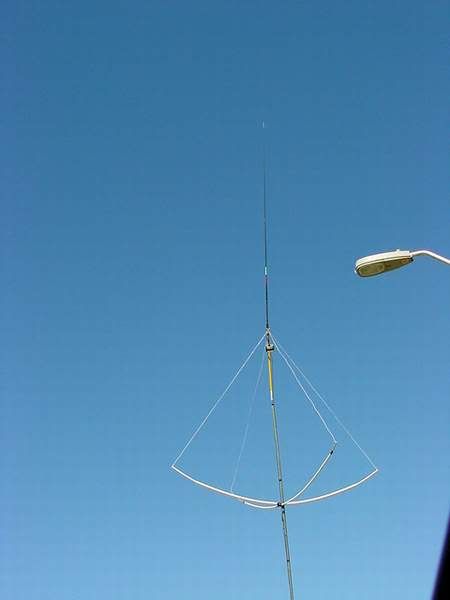 An alternative way of providing an antenna quickly would be thw 1/2 Wave Dipole. Everything is done exactly the same except you use one radial the exact same length as the vertical going in the opposite direction from the vertical. With this one you must be sure your coax runs away from the center connection point to the antenna 90° for an absolute minimum of 4' to prevent the coax from interacting with the antenna. The dipole can be run on its side, but keep it vertical to have the best performance on the CB band. Most other antennas used by CB'ers are run vertical so it makes a difference that you do the same or or may not be able to communicate with them. I do not recommend a separate grounding wire from this antenna to earth as it may complicate your match. If the antenna were on a pole you could ground the pole. Grounding your radio equipment from inside your shack to an earth ground is a good idea. 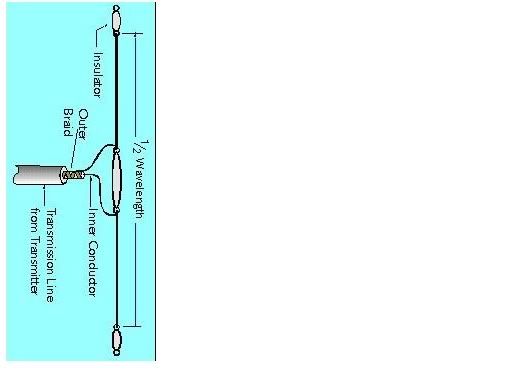 I might add that an easy way to accomplish this antenna is by using a plastic wall mount flag pole holder as high up on the facia of your house as you can get it. The copper tube would go into the holder pointing upward, and a wire could be allowed to hang downward for the lower radiator. To keep the wire stretched out its full length you can hang a non-conductive weight from the end of it, or pull it taut with a non-conductive tie off. Coax connection would be made at the center in the same fashion as shown in the diagram. 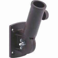 Good Luck, Charles |
|
|
|
Post by northernlights on Feb 8, 2011 12:25:15 GMT -5
Thanks Charles for the excellent refresher to antennas for me! I say "refresher" because a number of years ago, I was HEAVILY into CB radios, ham, and actually, antenna design and radiation pattern calculations were part of my previous line of work as an electronics tech at a few companies I worked for back in the 90s. but in the late 90's, I suffered a brain injury which robbed me of much of my "useful" memory, especially when it comes to electronics, which still to this day really bothers me, as I have the yearning to "do" electronic stuff, but find that I just do not have the knowledge I once had, and cannot seem to re-educate myself in terms of this kind of thing either due to my current memory issues as a result of the injury. Don't ever let a horse kick you in the head is my advice to you! I own a ton of electronics components still, which is nothing compared to what I USED to have years back, I've scaled it down substantially, and these days, I am actually into lapidary work, mostly cutting and polishing opals, and after years of doing "cabbing" work (which I sell on the internet and to a few other sources as a small business) I actually just bought a faceting machine, and hopefully can learn to "facet" gemstones as well. WAY off topic, but it just goes to show how FAR I've drifted away from the electronics industry unfortunately. The funny thing is that I sold off SO many components, as I never thought I'd have a need for them, and then, after selling off thousands of HF connectors, I go to get one, and cannot find ONE to connect my RG-213/U cable with, go figure...lol. I finally DID fine ONE, and one only, as well as a patch cord to connect my SWR meter to the CB also at least, so now, it's all connected up, but I'm just trying to figure out that's coming out of the antenna, if anything! I WAS actually able to talk to some truckers passing by, one could hear me and told me I had 4 bars on his RX, but the other guy was asking him "who" he was talking to, as he could not hear me at all, so I have no idea of the range, and since my 2 radios are acting totally opposite to one another, I'm wondering if one of them isn't working right, as I'm still confused as to WHY they act totally different when it comes to the frequency TX power levels. The TRC-433 base station seems to have more overall power than the Cobra does, and I actually took the Cobra out of my minivan (leaving it CB-less now) because nobody could even hear me unless they had a DIRECT line of sight with me as I was going down the highway, so again, I think this SAME antenna is to blame, possibly just being a CRAP antenna, so I think I'll take your advice and at least make a dipole or the copper pipe idea I had. The main confusion I had was about the ground radials, and what would happen without them, IF I would still have any RX/TX without them, and whether or not the grounding of the antenna ground to the copper pipe driven into the ground was a good idea or not. I remember the importance of the ground radials and proper grounding, as years ago, when I had a base station in my house out west in British Columbia when I lived there years ago, I actually dug up about 15 feet around the base of my antenna pole, and buried a layer of copper mesh all around the antenna pole to give a good ground "reflection", so I remember what I "did" in the past, just not what I "should" do right now, and since I'm at a rental, I'm not even sure more than a discrete little helical wound stubby stuck to the outside wall of the house is OK or not, so that always complicates things, I am sure the landlord is fine with it, as this dumpy little place needs a new roof and they aren't exactly jumping on doing that, and I'VE done more improvements here than THEY have lately, so they really shouldn't complain. I'm actually really just wanting to have emergency preparedness, and a way to communicate in case of emergency, I'm working on building a small wind turbine to connect to the 3 deep cycle batteries currently being charged by a couple 15W solar panels, so at least my rig is solar powered and does not rely on house power to run it! Thanks again for all your help, I've got LOTS more questions, but this post is already a BOOK, sorry about that! What I DO need is a refresher on how to actually USE my SWR meter, I'm "assuming" (yeah, I KNOW what that word REALLY means..lol) that when the dial is turned all the way counter clock-wise, that if there is no movement on the needle, then there is NO SWR? Thanks! Chris |
|
|
|
Post by homerbb on Feb 8, 2011 15:34:20 GMT -5
The "Realistic brand SWR" meter should have a rotating knob, and a switch labeled ref and cal.
Turn the knob all the way counter clockwise. Set the switch to CAL. While keying the microphone rotate the knob clockwise until the needle points to the spot on the gauge that says either cal or set. Now switch the switch over to REF (or fwd). The needle will reposition itself to the SWR you have. It is desirable to have a reading of 2.0:1 or less at ch 40 and ch 1. A reading of 1.5:1 or less is best. The meter face likely will not break it into the ratio readings, so they will be assumed in relation to the numbers you see on the gauge.
If the reading is lower on ch 1, the antenna's over all length is too long - shorten it. If the reading is lower on ch 40, the antenna's over all length needs to be extended - lengthen it.
It is a good idea to ground an antenna. Neither the dipole, nor the 1/4 ground plane will operate properly without radials. The dipole has two segments, one of them serves as your counterpoise (ie. ground plane). The mobile antenna you are using lacks a ground plane presently, and will not work properly with it. The automobile serves the purpose of the ground plane. Without a substantial metal GP, such as the automobile, beneath a mobile antenna they fail to operate properly. . . no one can hear you, and you may damage the output section of your transmitter by attempting to transmit through it.
|
|
|
|
Post by northernlights on Feb 8, 2011 16:37:58 GMT -5
Well, I figured "something" out anyhow! Oddly enough, my SWR meter had something wrong with the switch that goes from calibrate to SWR, one of the wires to the switch was OFF, so when I switched it from CAL to SWR, it just remained at 1, or zero, basically showing NO standing wave at all, but in reality, what REALLY is going on when I soldered that wire on (it's really weird, the SWR meter is an old Radio shack one NEW in the box that I bought at the flea market) suddenly, I can see that on channel 1 on my base station, there is a reading of around 1.75 on the SWR meter, but on channel 40, it is like 1.1, barely showing anything, so it makes sense to me now WHY there is so much more power output showing on the bars on the base when it is on one channel as opposed to the other, there is a higher SWR reading on the one channel, thus resulting in less power output, right?? It's funny how it's the EXACT opposire when I put the Cobra mobile on the meter with that antenna setup I currently have, wonder why that is? Anyhow, what I guess i should do rather than muck about with the crappy antenna setup I currently have it to REPLACE it with one if the ones suggested, and THEN try it again, and THEN deal with any standing wave issues i might encounter after that. Sorry to bug you guys about a stupid issue with a piece of my equipment you could not possibly know about or suggest how to fix, something just told me to look at the inside of that SWR meter, now I know why. It was probably buggered from the factory, and sat in someone's attic new in the box after they tried it once and it didn't work, until the day I bought it for 3 bucks at the flea market...lol. I'll let you all know what happens after I connect the 105" piece of copper tubing to see how it works out, so, what size ground radials should I use if I go with a 105" piece of copper tubing as the antenna, and how many ground radials should I use? It's kinda ridiculous to have this big 100 foot coil of RG-213/U coax sitting in the middle of my floor when the antenna is just 10 feet away from the CB, but I don't have a tall mast to mount the antenna on, and I figured I might as well use the big heavy duty piece of coax I have just laying here, when the one on my antenna was a POS and needed to be replaced anyhow. At least I'll be ready if I happen to purchase a 500W foot warmer or something...lol. thanks all, Chris |
|
|
|
Post by northernlights on Feb 8, 2011 16:41:00 GMT -5
Oh, BTW, what CAN I do about a high SWR like this if I can't really "fix" the antenna, do I need a matching balun or something? Is there an LC network or bridge I could rig up with a variable cap and an inductor or something to fix things if for some odd reason, the antenna is made perfectly as it should be, but there is a high SWR? Also, should I solder an end cap on the standard 1/2" copper plumbing pipe that I use for an antenna, will it make a difference in the TX at all? Chris |
|
|
|
Post by homerbb on Feb 8, 2011 18:12:41 GMT -5
There is no reason to sweat the SWR as it is. You are not going to improve the set up based on the SWR alone, and it is good enough like it is.
as far as your radios reading differently on opposite ends, there could be reasons within each radio in terms of the way the tune has (or has not) been done to each radio.
Use four radials for the 1/4 wave GP, or just make a 1/2 wave dipole. The 1/2 wave is a larger antenna electrically, while physically it is smaller. It will likely give you back more.
That 100' of coax curled up in a roll may be depriving you of power out the antenna. I can't say for sure the exact effect it may have, but that coil matters. It would be so much better if you'd solder a new end on a shorter piece of the coax using only as much as it takes to get from the transmitter to the antenna. The length you're using of the type of coax you've got has very little loss, it's a good coax, but that coil is not a thing I'd want to work my signal through.
|
|
|
|
Post by northernlights on Feb 8, 2011 20:49:30 GMT -5
Yeah, your probably right, I kinda wanted to keep the coax in one length, but given the choice between that and going out and "buying" another piece of crappier RG58 or something, I think I would rather just lop off the end of this long length of RG-213/U and I'll still have one long length left. Thanks! Chris |
|
|
|
Post by northernlights on Feb 9, 2011 16:46:30 GMT -5
So I have another question if you don't mind me asking. What would happen if you took that 100' piece of RG-213/U cable, an at the end where the antenna is currently connected, you cut off the antenna, and then you removed the outer insulation, and the outer copper brain shield also, leaving 105 inches of ONLY the center copper conductor and it's thick nylon insulation around the center conductor, then, added the appropriate ground planes or the other half of the dipole (depending on what kind of antenna you want) to the outer braided copper coax shielding. Would continuing on the appropriate length of only the center conductor at the end of a piece of coax, while removing it's jacket insulation and copper shielding be the exact same as connecting a 105" piece of copper tubing, or wire, or whatever you were wanting to make the antenna out of, or does a "proper" antenna somehow rely on there bring a "cut" in the coax, and then "connecting" an extended "antenna" to that cut end of the coax? I hope I'm explaining it properly so that you can understand my question! I guess what I'm wondering is why do I need to "add" a piece of copper conductor cut to the length of the proper antenna length, (in this case 105"), to the end of the length of coax attached to the CB radio, when there already IS a copper conductor right inside the coax itself? It seems logical that you should just be able to peel back the outer cable jacket and remove the copper braided shielding back to whatever antenna length you need, and that would "electrically" be the same as ADDING a piece of conductor as an antenna to the coax. Would this work ok? For example, to make a dipole antenna, I would remove the 105 inches of outer jacket of the coax, and the braided shielding, and cut that off, leaving only the 105" on the center conductor with it's inner nylon insulation hanging out, then attach a equal length piece of copper wire to the copper braided shield where it was cut off, and then just simply hang those in opposite directions to form a dipole antenna. I would actually just even leave the braided copper shield ON without cutting it off, leaving it as if the center conductor and the braided copper shield were simply split off in separate directions if I knew I could keep the braid in all one piece somehow when I removed it to expose the center core, but since that probably is not possible, I just planned on cutting it off and soldering on to the copper braid where I cut it off a piece of copper wire instead. So what do you think, would this work fine? If not, why? Thanks! Chris |
|
|
|
Post by homerbb on Feb 9, 2011 19:54:17 GMT -5
You can make a dipole by doing exactly as you said, but do not cut off the braid shield. Push backward on the braid loosening it up. Open a spot in the braid near where the outer coating of the coax you cut off begins. Pull your inner conductor out through that. You have a dipole made from the inner conductor going one direction, the braid shield going the other. You can do exactly the same but instead of pulling the inner conductor out the side of the shield you roll the entire shield back down over the coax until it completely covers the coax backward from the point you cut off the outer covering of the coax. This is a coaxial sleeve dipole. And you can do exactly as you asked about. 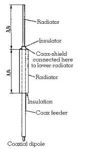 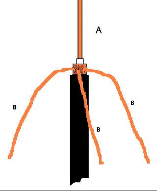 |
|
|
|
Post by northernlights on Feb 10, 2011 15:01:09 GMT -5
Kewl, I invented something that's already been invented, not gonna make any money THAT way, hahaha! Thanks for posting that! Awesome help !! Chris |
|
|
|
Post by homerbb on Feb 15, 2011 12:21:20 GMT -5
northernlights, how's your project going?
|
|
|
|
Post by northernlights on Feb 21, 2011 11:02:21 GMT -5
Well, actually it's "not" going anywhere right now! Having 2 feet of snow on the roof, and 3 or 4 feet on the ground that won't even allow me to walk to the other side of the house is kinda putting a damper on things!! Once it warms up a bit, and i can "reach" anywhere other than the 3 feet outside my back door on the outside of the house where I currently have the little maggy mount on a stick mounted, then I'll be able to DO something...LOL Thanks! Chris |
|
|
|
Post by northernlights on Feb 21, 2011 11:05:14 GMT -5
Oh, BTW, oddly, I had 4 ground radials soldered to the underside of that helical wound stubbie magnetic mount antenna which I had to remove the rust mount from, and was left with the stub that was about 14 inches long, and after removing those ground radials, which were not shorted or anything, my SWR dropped drastically. Now WHY would THAT be? How could a ground radial cause a high SWR? Was it reflecting the wave back down into the antenna and transmission line somehow? Weird! Chris |
|
|
|
Post by homerbb on Feb 21, 2011 15:59:11 GMT -5
Oh, BTW, oddly, I had 4 ground radials soldered to the underside of that helical wound stubbie magnetic mount antenna which I had to remove the rust mount from, and was left with the stub that was about 14 inches long, and after removing those ground radials, which were not shorted or anything, my SWR dropped drastically. Now WHY would THAT be? How could a ground radial cause a high SWR? Was it reflecting the wave back down into the antenna and transmission line somehow? Weird! Chris Without actually seeing what you had it is just a guess, but I think the reason could be that the 4 wire ground plane helped to isolate the coax from the antenna. The vertical portion of the antenna was not well matched to the coax/transmitter - higher SWR. When once the GP was removed, the coax became a part of your radiator/vertical antenna bringing the SWR down. This is not uncommon. There are antennas that purposely use the coax to make them work. They are not usually the best of antennas. |
|