|
|
Post by homerbb on Aug 17, 2011 19:48:32 GMT -5
I picked up this radio, Royce 1-641, for a fair price. According to some sources online it won't modify to additional channels having a closed pll, however, it is already done and appear to be working. Dirty switches and knobs I fixed with cleaner, and I replaced a bad SPST switch. It had been dropped and the inline AC fuse holder on the back was broken. I rewired a Courier Dynamic desk mic for it, and now wait for conditions to check it out. You'll notice the three SPST switches on the bottom of the unit for channel options. I will put the freq counter inline tomorrow and write down the road map. 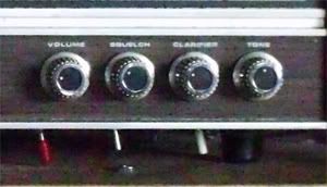 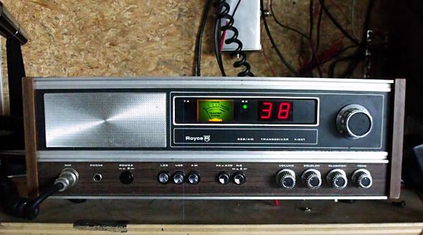 |
|
|
|
Post by cbrown on Aug 18, 2011 9:07:37 GMT -5
Ah yes, the old 'sardine can' sealed PLL. ;D Can't modify it of you can't get at it, right?
Wrong. You just change the loop mixing crystal.
Let us know what the range is on that unit.
|
|
|
|
Post by homerbb on Aug 18, 2011 13:49:30 GMT -5
I'll do it; probably later this evening. 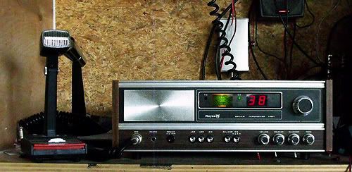 |
|
|
|
Post by homerbb on Aug 19, 2011 11:03:06 GMT -5
I mapped this radio, and it is odd: 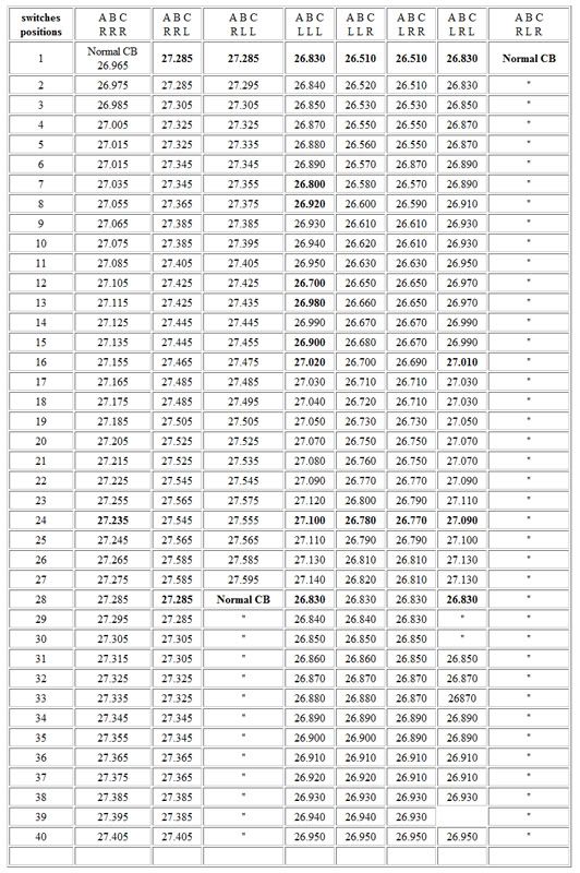 |
|
Sandbagger
Administrator/The Boss 
Posts: 6,249 
|
Post by Sandbagger on Aug 19, 2011 14:48:24 GMT -5
The Royce 40 channel PLL radios were all fairly easy to modify, but the PLL chips that they used were not all that capable. The were typically only a 64 word program (64 total channels), usually starting at channel 1 and ending at channel 59. Those even frequency channels below one suggest that some crystal swappage was going on as well. Reminds me of the old reversing the I.F. crystal trick we used to do to the 23 channel AM rigs......
|
|
|
|
Post by homerbb on Aug 19, 2011 16:48:51 GMT -5
Fortunately below 40 is not a place I frequently go.
|
|
|
|
Post by cbrown on Aug 22, 2011 9:01:56 GMT -5
I'd agree with Sandbagger, the mapping of the frequencies in the first group (nothing above 27.595 MHz) suggests the PLL was accessed.
And with the next mapping (below Ch. 1, 26.965 Mhz) with all frequencies ending in a zero would suggest a crystal addition. But unless whomever you are planning on talking to has a VFO, it'll be tough to use those frequencies.
Did you pull the cover and see what the wires were connected to?
|
|
|
|
Post by homerbb on Aug 22, 2011 10:18:42 GMT -5
I'd agree with Sandbagger, the mapping of the frequencies in the first group (nothing above 27.595 MHz) suggests the PLL was accessed. And with the next mapping (below Ch. 1, 26.965 Mhz) with all frequencies ending in a zero would suggest a crystal addition. But unless whomever you are planning on talking to has a VFO, it'll be tough to use those frequencies. Did you pull the cover and see what the wires were connected to? Yes, I pulled the cover. I will take some photos if you wish. If I could take it back to original I might do so. These skipped and oddball 5Khz channels do not excite me at all. |
|
|
|
Post by cbrown on Aug 23, 2011 8:50:22 GMT -5
Yes, I pulled the cover. I will take some photos if you wish. If I could take it back to original I might do so. These skipped and oddball 5Khz channels do not excite me at all. Don't put yourself out if you don't want to, I'm always curious on the way people modify their radios.  Depending on how they wired the switches, I don't really foresee a problem getting the radio back to stock if that is what you want to do. |
|
|
|
Post by homerbb on Aug 23, 2011 20:32:43 GMT -5
I'll be looking into returning it to stock. As it is I find it less appealing, and the tune on the freqs is less than clean on both AM and SSB. When I open it gain I'll take some photos for you.
|
|
Sandbagger
Administrator/The Boss
Posts: 6,249
|
Post by Sandbagger on Aug 23, 2011 21:14:36 GMT -5
I'll be looking into returning it to stock. As it is I find it less appealing, and the tune on the freqs is less than clean on both AM and SSB. When I open it gain I'll take some photos for you. I find that I far prefer vintage radios to be as close to factory stock as possible. They usually will work better, and be far more stable and clean in RF output. I have no need for a modified CB radio as I have highly capable ham rigs which can go anywhere I might want to go outside of the CB band.I enjoy running my vintage classic rigs where they were intended. The only exception I might make, is to pull one crystal out of a 23 channel SSB radio and exchange it for one that will allow operation on channels 36 - 40, so I can use the SSB portion more regularly. |
|
|
|
Post by cbrown on Aug 24, 2011 9:05:17 GMT -5
I have no need for a modified CB radio as I have highly capable ham rigs which can go anywhere I might want to go outside of the CB band.I enjoy running my vintage classic rigs where they were intended. The only exception I might make, is to pull one crystal out of a 23 channel SSB radio and exchange it for one that will allow operation on channels 36 - 40, so I can use the SSB portion more regularly. Well said!  |
|
|
|
Post by homerbb on Aug 24, 2011 9:15:55 GMT -5
Exactly how I feel about this radio, too.
|
|
|
|
Post by homerbb on Aug 25, 2011 12:30:07 GMT -5
Three photos of the Royce with jumpers on the bottom of the board to the switches. 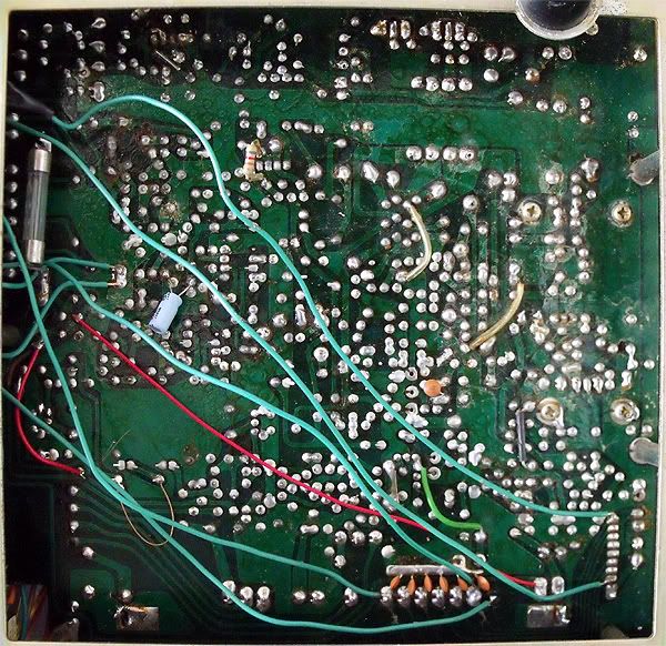 Upper board view: 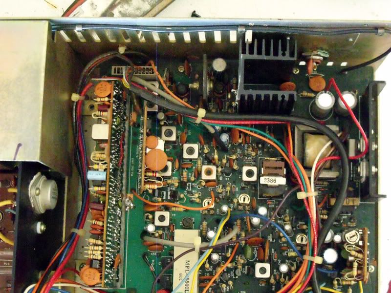 PLL can lid off': 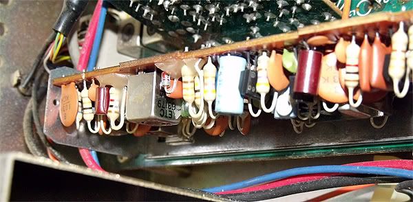 |
|
Sandbagger
Administrator/The Boss
Posts: 6,249
|
Post by Sandbagger on Aug 25, 2011 20:14:00 GMT -5
Three photos of the Royce with jumpers on the bottom of the board to the switches. Upper board view: PLL can lid off': What a mess...... I can see the PLL switch. There's only one pin that makes any difference on those Royce's. I can't tell what the other wires are doing, but I'm assuming they're swapping crystals.But I have to wonder if both SSB modes work when the crystals are swapped....... |
|
|
|
Post by homerbb on Aug 25, 2011 21:37:23 GMT -5
My question would be whether if I took these wires off I'd be back to normal, or if theve swapped parts in places I can't determine.
I want to take the switches off, so I quess I'll just mark them to where they currently are and pull them to see where the radio lands. I may need to retune to put it back on frequency, so which components does what in this radio is a matter for research if so . . .
Those extra switches get me additional lowers with 5Khz off the normal frequencies at 10 Khz jumps most of the time.
I also think the clarifier has been adjusted as straight up on the tx/rx occurs at about 10:30 o'clock on the clarifier knob.
|
|
Sandbagger
Administrator/The Boss
Posts: 6,249
|
Post by Sandbagger on Aug 26, 2011 6:45:03 GMT -5
My question would be whether if I took these wires off I'd be back to normal, or if theve swapped parts in places I can't determine. I want to take the switches off, so I quess I'll just mark them to where they currently are and pull them to see where the radio lands. I may need to retune to put it back on frequency, so which components does what in this radio is a matter for research if so . . . Those extra switches get me additional lowers with 5Khz off the normal frequencies at 10 Khz jumps most of the time. I also think the clarifier has been adjusted as straight up on the tx/rx occurs at about 10:30 o'clock on the clarifier knob. Well, you can remove the wires to the PLL. Nothing will be affected there as the switch only adds 5V on that pin to give you from channels 42 to 59. As for the others, I can't determine from the photos whether other "stuff" was done that would be rendered inoperative if you simply disconnected the switches. It doesn't look like there were any strange parts added though, so you might be ok. You can try disconnecting the switches and see if things stay working. You may have to re-connect hard wires to the "normal" side of the switch if it stops working with all of the wires disconnected. |
|
|
|
Post by homerbb on Aug 26, 2011 8:13:26 GMT -5
I'm gonna try that. I'll take off all but the PLL switch. If all goes well, I may leave that in place for the few channels of uppers. We'll see.
|
|
|
|
Post by cbrown on Aug 26, 2011 8:54:31 GMT -5
How many wires are hooked to each switch?
If its just two, you're pretty safe just removing everything.
|
|
|
|
Post by homerbb on Aug 26, 2011 12:17:23 GMT -5
I removed them all, and the rig is stuck with the channels in the column 2 mode - ABC = RRL
|
|
|
|
Post by homerbb on Aug 26, 2011 14:55:33 GMT -5
I noticed there were a couple traces from the PLL cut, so I figured that would have something to do with the way the removal of the switches caused the frequencies to land. Putting them back together did the trick, but in the process of figuring things out I noticed I could get a 10Khz jump with a jumper, so I left a switch in for that. Additionally, I decided to leave a switch in place to get a set of uppers. A simple removal of the switch and a trace reconnection would put it back to stock should I want to do so. Now there are only two switches, one for 10k jump, the other for the frequencies in column ABC/RLL. As you can see from the photo, the clarifier has to be on 10:00 o'clock position to obtain frequency center. I need to learn where the frequency adjustments are to bring that back to center. 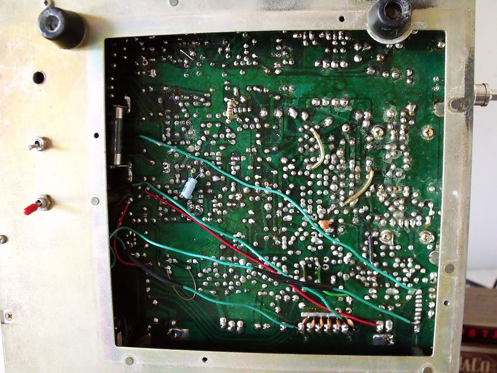 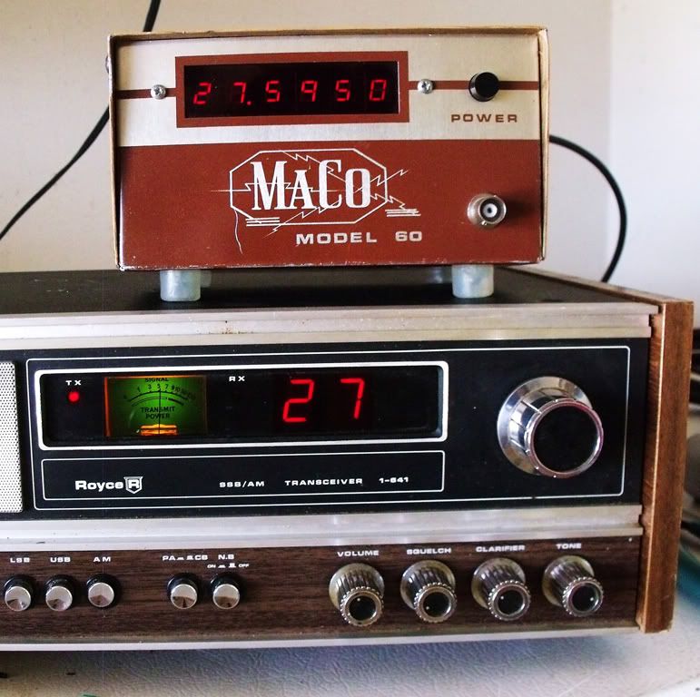 |
|
|
|
Post by homerbb on Aug 29, 2011 22:08:06 GMT -5
I left the clarifier alone. I looked it over and realized it was a simple matter of reconnecting the R99 that was cut, and moving the pink wire on the back of the clarifier knob from the 9v power source to its original location should it prove necessary to reverse the mod.
I wired a Turner +2 microphone, found and touched up some cold solder joints, and test drove it again. I received good reports on the sound quality of the radio using the Turner over the old Courier switching them back and forth for comparison.
I am feeling better and fonder of the old Royce bit by bit.
|
|
Sandbagger
Administrator/The Boss
Posts: 6,249
|
Post by Sandbagger on Aug 30, 2011 6:12:28 GMT -5
I left the clarifier alone. I looked it over and realized it was a simple matter of reconnecting the R99 that was cut, and moving the pink wire on the back of the clarifier knob from the 9v power source to its original location should it prove necessary to reverse the mod. I wired a Turner +2 microphone, found and touched up some cold solder joints, and test drove it again. I received good reports on the sound quality of the radio using the Tuner over the old Courier switching them back and forth for comparison. I am feeling better and fonder of the old Royce bit by bit. I'd leave the clarifier modified. The factory stock configuration is locked transmit, reciever tune only, which basically sucks in a roundtable situation. If the fact that center slot is not in the 12-O'clock position, that can be rectified by either alignment, or resistor padding across the pot to re-center the range. I liked the Royce radios. Some of them had really good receiver designs and they worked well. |
|
|
|
Post by homerbb on Aug 30, 2011 7:59:59 GMT -5
If I knew which pots to use for realignment i might give it a go, but think the resistor padding would be best so i don't have to twist anything. Could you explain which, where, and how easily?
As for receive, this radio seems to have great ears.
|
|
Sandbagger
Administrator/The Boss
Posts: 6,249
|
Post by Sandbagger on Aug 31, 2011 6:27:43 GMT -5
If I knew which pots to use for realignment i might give it a go, but think the resistor padding would be best so i don't have to twist anything. Could you explain which, where, and how easily? As for receive, this radio seems to have great ears. Well, what I usually do with the clarifier is to first check the total range (+/-) and try to align the oscillator for an even split (+/- 2 Khz or whatever). Sometimes, even when you do this, the "center slot", 12 O'clock position is not dead center on-frequency. In the case of the clarifier being off to the + side (2 O'clock etc.), I usually take a small trimpot in the 10 - 20K range and put it from the hot side of the clarifier pot to the wiper of the clarifier pot. I then adjust the trimpot until center slot lines up on frequency. If you're off to the (-) side (10 O'clock) then the trimpot should be placed between the wiper and the ground side of the clarifier pot, and adjusted similarly. Additionally, if you'd prefer, once the trim pot is adjusted for the proper center-slot frequency, you can remove it and measure the resistance, and then find a fixed value resistor of the same resistance value and solder that to the clarifier pot for a cleaner appearance. |
|
|
|
Post by homerbb on Aug 31, 2011 13:24:05 GMT -5
That's extremely helpful, and simple. When I find the exact pot to set the center with, I'll go from there with the VR to fix my knob center.
I'll check it again, but when I last did the slide was 4/1 toward the lower frequency.
Thanks!
|
|