|
|
Post by homerbb on Nov 17, 2011 0:14:35 GMT -5
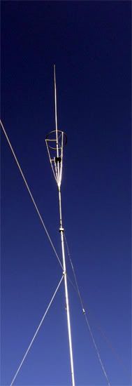
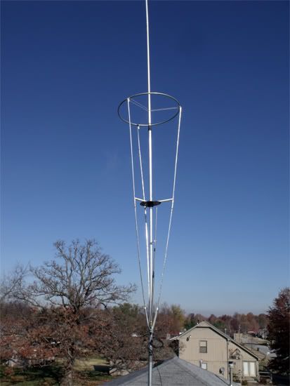
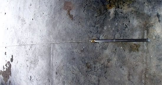
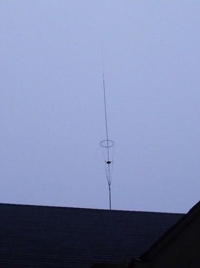
I decided to use the materials I had at hand to make another antenna to replace the Qv4k I had traded away for a radio I wanted. I knew I could always make another antenna, and lacked the skills to build a radio. So I did. Here is the Made in the USA SigmaIV This antenna is built virtually identically to the SigmaIV discussed in at least two prominent threads on this forum. The only significant difference is the ring is slightly smaller in diameter because it is preformed and served to get the project kicked off.  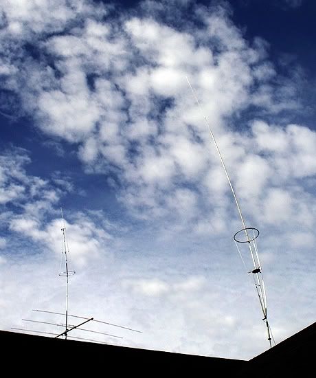 It's very windy today! It's very windy today!More later. Time to go to the Home Depot and earn a living. More adjusting to do later, But here is SWR bandwidth with MFJ-209 at the shack end of the coax. 2.1:1 ---------------------- 28.155 1.5:1 ---------------------- 27.840 1.0:1 ---------------------- 27.565 1.0:1 ---------------------- 27.555 1.0:1 ---------------------- 27.445 1.5:1 ---------------------- 27.085 2.1:1 ---------------------- 26.600 Initially, it appears to be less widebanded than the Qv4k, but I will have to look that up and do some more adjusting. It is 4 feet above the roof ridge for now - 23' from the ground. |
|
Sandbagger
Administrator/The Boss 
Posts: 6,250 
|
Post by Sandbagger on Nov 17, 2011 7:58:53 GMT -5
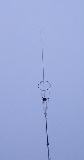
I decided to use the materials I had at hand to make another antenna to replace the Qv4k I had traded away for a radio I wanted. I knew I could always make another antenna, and lacked the skills to build a radio. So I did. Here is the Made in the USA SigmaIV This antenna is built virtually identically to the SigmaIV discussed in at least two prominent threads on this forum. The only significant difference is the ring is slightly smaller in diameter because it is preformed and served to get the project kicked off. It's very windy today!More later. Time to go to the Home Depot and earn a living. More adjusting to do later, But here is SWR bandwidth with MFJ-209 at the shack end of the coax. 2.1:1 ---------------------- 28.155 1.5:1 ---------------------- 27.840 1.0:1 ---------------------- 27.565 1.0:1 ---------------------- 27.555 1.0:1 ---------------------- 27.445 1.5:1 ---------------------- 27.085 2.1:1 ---------------------- 26.600 Initially, it appears to be less widebanded than the Qv4k, but I will have to look that up and do some more adjusting. It is 4 feet above the roof ridge for now - 23' from the ground. Looking good! |
|
|
|
Post by cbrown on Nov 17, 2011 10:01:00 GMT -5
A 1.55 MHz bandwidth isn't bad at all, Homer. Looks very good, too!
|
|
|
|
Post by Sniper..Unit 305 on Nov 17, 2011 10:19:38 GMT -5
Really looks good! Is it true or did I just come up with this idea in my head somehow, but doesn't a broad banded antenna have less gain than a more narrow banded one? If it's true, then you ought to be pretty darn good where it is now. Where did I get this idea, did I read it somewhere, hear it somewhere? I haven't a clue....lol !! Sniper
|
|
|
|
Post by homerbb on Nov 17, 2011 10:35:40 GMT -5
Others may chime in on this, but I've heard that, too.
This came up in a discussion of which I was a part with respect to this particular type antenna. Because of the way this antenna is built the general consensus was there can be exceptions due to design up to a point. At some point the antenna has not been made resonant within a certain set of frequencies. When that occurs, if I correctly recall, then the low SWR is due to losses in the antenna due to design, rather than a good match.
As an example of this I placed and tuned a well made long center load antenna on top of my mobile and got a good SWR. Next I place a three foot no-load straight fiberglass antenna on my mobile on the same puck mount. This antenna also has a good SWR. The first was resonant and well designed. The second being so radically shorter was obtaining a low reading due to losses to ground. It's about finding resonance in the design of the antenna, not just a low SWR.
That's why I prefer to use the analyzer over the SWR meter as its circuitry measures more than a simple meter to produce the result.
|
|
|
|
Post by homerbb on Nov 17, 2011 13:30:24 GMT -5
|
|
|
|
Post by Sniper..Unit 305 on Nov 17, 2011 23:15:32 GMT -5
Thanks homerbb, I thought I heard that somewhere...sometime !!
Sniper
|
|
|
|
Post by homerbb on Nov 18, 2011 9:24:33 GMT -5
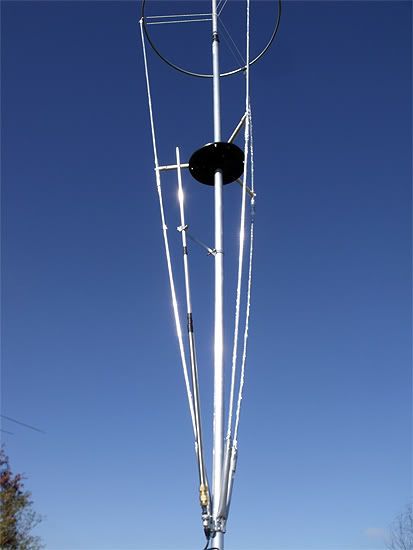
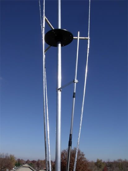
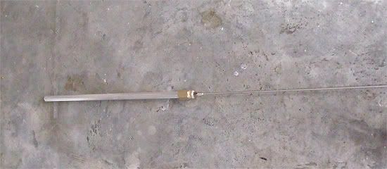
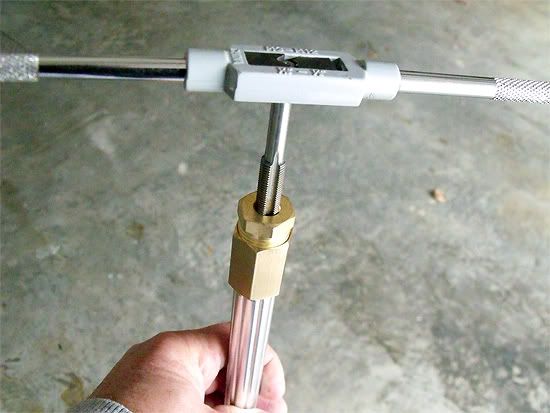
You're welcome, Sniper. As a matter of interest to those looking for a stout way to mount a gamma: As for the bottom of the gamma, what you see there comes from making the mobile antennas. For a person without a true fabrication facility getting a mobile antenna together was not too much a problem, but finding a way to securely attach it to the mounting bracket was challenging. I tried various things until I eventually landed on a combination of a brass compression fitting and the brass reducing bushing. The pipe threads in the brass reducer are the same as those on a standard 3/8" fine thread stud used with antennas except pipe thread tapers slightly. I use a 3/8" thread tap for bolts to chase the threads straight. once done, I merely thread a bolt from the top side of the reducer bushing into a standard mount, as you see it done in the photo. I migrated the same process over to the gamma for use here, and that will likely be the manner of mounting all my gammas for all types antennas in the future. Notice the bottom of the homebrew mobile. the bottom tube of one of these is what the gamma is (of proper length, of course). 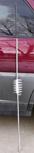 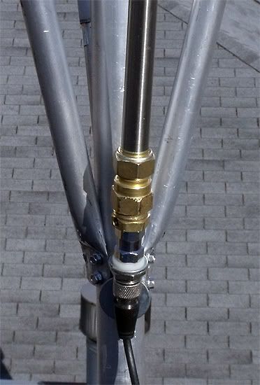 |
|
|
|
Post by cbrown on Nov 18, 2011 9:57:22 GMT -5
Buy some Coax Seal, and use it around all those tread connections Homer. It stays flexible in case you have to remove it (unlike the tar was used to use).
That antenna looks great! Let us know how it works.
|
|
|
|
Post by homerbb on Nov 18, 2011 10:22:50 GMT -5
Good idea on the coax seal.
The antenna has a propensity for being noisier than both the Astroplane and the beam. It is very quiet without the preamp on, whereas the other two antennas handle preamp without added white noise. However, it seems to do well so far. Today's conditions are not very good into NW Arkansas, so I am still out with a verdict.
In spite of poor conditions I've managed a few contacts with unsolicited good comments on the other end not using a preamp. I will keep monitoring under various conditions, but the homebrew AP is tougher competition than many folks will admit.
|
|
|
|
Post by homerbb on Nov 18, 2011 22:10:04 GMT -5
Should anyone get inspired to try this, the materials are simple. Tubing: start with minimum diameter of 1-1/4" for bottom section and have a finished total length of 28' 7" when all are joined together from largest at bottom to smallest at top. Radials: three or four tubes/rods that are each 7' 6.5" long - you can use fiberglass rods, cane poles, (wrapped with aluminum duct tape) aluminum tube etc. Ring: 29.5" to 30" diameter - you can make this of PEX tubing wrapped with aluminum tape, or even flat aluminum stock. Angle for feedpoint where coax connector is mounted - this can be a pre-made mobile antenna bracket, or fabricate one from metal. Antenna coax connector from mobile antenna. Gamma Match - 1/2" ID x 17.5" tube. 3/16" x 34" rod. 1/4" ID x 3/8" OD rubber tube for gamma rod insulator. Gamma connector - brass compression connector and brass 1/2" PT x 3/8" brass bushing for gamma connection to coax connector. (Read how-to in above post.) Aluminum mechanical lug* for top of gamma rod and aluminum strap for gamma tap. Various screws and clamps for joints.You're ready to go. *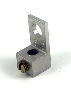 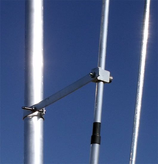 Make the bottom of the radials 12" up from the bottom end of the vertical. |
|
|
|
Post by homerbb on Nov 19, 2011 12:34:40 GMT -5
I had reported that there seemed to be excessive white noise on the SigmaIV when pre-amp was on.
I need to make a correction here. In spite of how embarrassing it can be, I was hearing this whote noise increase on the loop in the attic. I had switched the coaxes on the antenna switch and forgotten. back tracking the wires through the attic confirmed this for me.
On the other hand, another discovery is that I had put a bad coax in line with the SigmaIV. I can not get it down until this wind stops. I have tried in high winds only to have the wind stand the tower back upright. I need to put a good coax in line. In the meantime, I am on the loop in the attic. The AP is on the ground, and the 4el beam is tied to the fence sitting on the reflector with the beam pointed straight at the sky.
Weather permitting, I will fix it Monday and get back on target.
I'm very put out with myself . . .
|
|
|
|
Post by homerbb on Nov 19, 2011 17:20:20 GMT -5
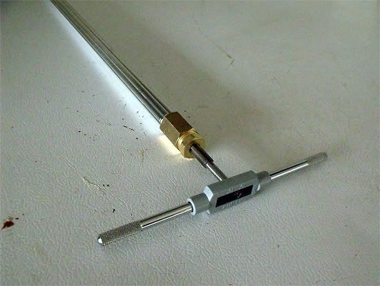
Here's the exploded view of the bottom connector setup for the gamma match: 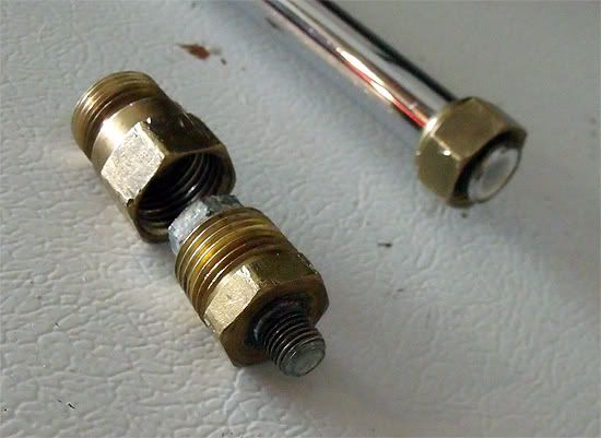 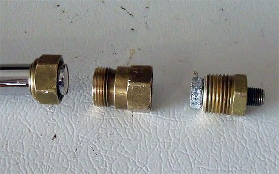 |
|
Sandbagger
Administrator/The Boss
Posts: 6,250
|
Post by Sandbagger on Nov 19, 2011 21:19:04 GMT -5
Here's the exploded view of the bottom connector setup for the gamma match: Talk about a plumber's delight. But you get an A+ for your innovative solution...... |
|
|
|
Post by homerbb on Nov 20, 2011 0:21:08 GMT -5
Thank you for the good grade. Better than I usually got in school.
|
|
|
|
Post by cbrown on Nov 21, 2011 9:56:37 GMT -5
the 4el beam is tied to the fence sitting on the reflector with the beam pointed straight at the sky. Now is your chance to try the 11 meter EME bounce!  |
|
|
|
Post by homerbb on Nov 21, 2011 10:42:05 GMT -5
|
|
|
|
Post by homerbb on Nov 21, 2011 20:17:49 GMT -5
|
|