Digital frequency display for a really old Pace 1000B
Jul 4, 2016 16:49:17 GMT -5
cbrown, BBB, and 2 more like this
Post by 2600 on Jul 4, 2016 16:49:17 GMT -5
I posted this on the CB Tricks forum. But seeing as how new signups have been disabled there for some time, it made sense to repost it here.
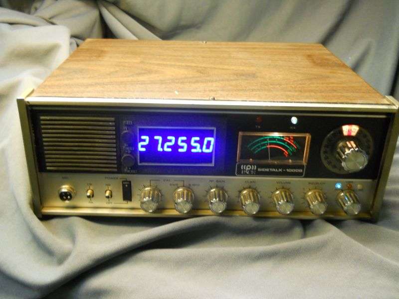
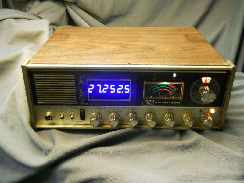
This is not the sexiest base radio ever. But it had a mechanical clock and the customer wanted a counter display in that window. The extra channels in this radio were a pain in the neck without one, he said.
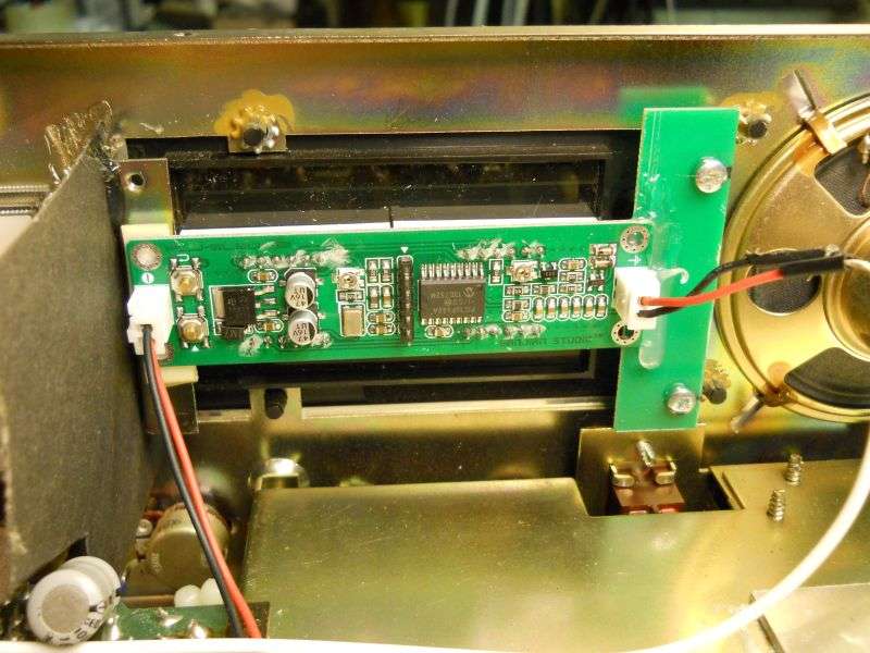
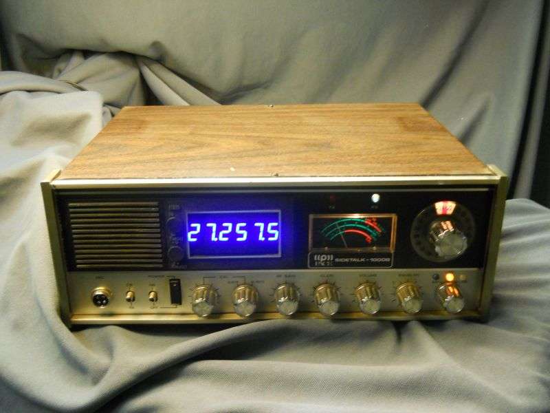
The SanJian 6-digit LED counter/display just barely fits in the 3-inch wide window. Cut a piece of smoked plex to improve the contrast of the too-bright digits and hide the counter's works, at least a little.
First problem you may have encountered with these displays is the input sensitivity and low input impedance. Hooking it directly to the output of a radio's synthesizer tends to load down the local-oscillator (LO) signal. You'll know this happens when touching the counter's input wire to the radio causes the receiver's signal level to drop. If you see that, you can be fairly confident your transmit power will also be reduced.
The other limitation of these otherwise-fine displays has to do with the display's supply voltage. They tell you the max is 9 Volts DC. This is because of the 5-Volt SMT regulator on the display's pc board. It has a tiny heat budget. The higher the power-supply voltage, the more heat it throws. 9 Volts is okay, but 8 Volts seems to be the sweet spot. If the radio's built-in 8-Volt regulator can supply the extra current to run one of these, that's fine. But most radios won't have that extra capacity. The 7808T regulator we used here is soldered directly to the ground foil on this radio. The tiny TO-92 version of this regulator is not quite big enough to power this display. The TO-220 part is overkill, but about the same price as the small version. The board foil it's soldered to provides plenty of heat sinking, and simplifies getting it mounted. The 10uf electrolytic on the output is to keep the regulator stable. They will sometimes oscillate and cause headaches without this capacitor. The input-side terminal is soldered right to the radio's large filter capacitor, so it won't need one added to its input pin.
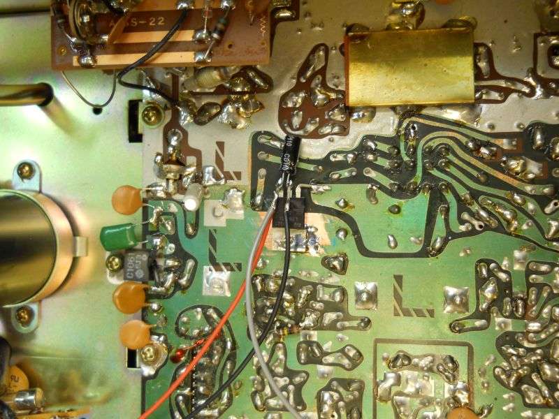
Rather than diddle with the counter's input circuit, I added a JFET buffer amp. It does not provide any voltage gain, only current gain. The disc capacitor feeding the gate of the JFET is 8.2pf. Won't reduce the LO drive voltage to the radio's mixer circuits. The size of this cap is not critical, and there's probably a LOT of leeway to the values that will work.
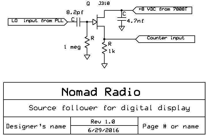
All it really provides is an impedance step down. The circuit's input impedance is pretty high, so the radio's LO output level is not loaded down. The output voltage to the counter is only a little less than the input, but has more than enough drive current for the input of the counter.
Really should have selected aperture priority to get some depth-of-field and used the tripod to make this clearer, but this is how it's built in this radio.
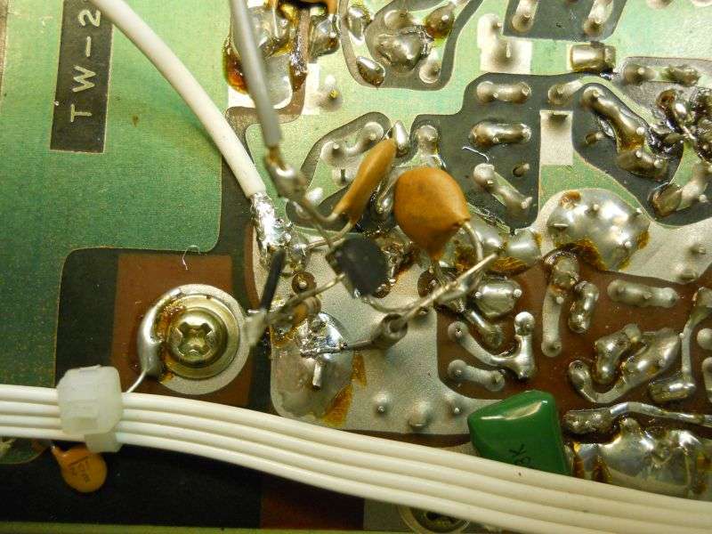
Not pretty, but solid enough for a base station. Might not hold up well in a mobile.
Of course it only reads correctly in AM mode. No way to correct for the carrier-frequency change in USB.
Or LSB
The buffer is a simple solution to the mismatch between the counter's input-drive requirements and the LO-circuit power that we can "borrow" to drive its input without reducing the radio's performance.
Made the customer happy, and that's the objective, after all.
73
This is not the sexiest base radio ever. But it had a mechanical clock and the customer wanted a counter display in that window. The extra channels in this radio were a pain in the neck without one, he said.
The SanJian 6-digit LED counter/display just barely fits in the 3-inch wide window. Cut a piece of smoked plex to improve the contrast of the too-bright digits and hide the counter's works, at least a little.


First problem you may have encountered with these displays is the input sensitivity and low input impedance. Hooking it directly to the output of a radio's synthesizer tends to load down the local-oscillator (LO) signal. You'll know this happens when touching the counter's input wire to the radio causes the receiver's signal level to drop. If you see that, you can be fairly confident your transmit power will also be reduced.
The other limitation of these otherwise-fine displays has to do with the display's supply voltage. They tell you the max is 9 Volts DC. This is because of the 5-Volt SMT regulator on the display's pc board. It has a tiny heat budget. The higher the power-supply voltage, the more heat it throws. 9 Volts is okay, but 8 Volts seems to be the sweet spot. If the radio's built-in 8-Volt regulator can supply the extra current to run one of these, that's fine. But most radios won't have that extra capacity. The 7808T regulator we used here is soldered directly to the ground foil on this radio. The tiny TO-92 version of this regulator is not quite big enough to power this display. The TO-220 part is overkill, but about the same price as the small version. The board foil it's soldered to provides plenty of heat sinking, and simplifies getting it mounted. The 10uf electrolytic on the output is to keep the regulator stable. They will sometimes oscillate and cause headaches without this capacitor. The input-side terminal is soldered right to the radio's large filter capacitor, so it won't need one added to its input pin.

Rather than diddle with the counter's input circuit, I added a JFET buffer amp. It does not provide any voltage gain, only current gain. The disc capacitor feeding the gate of the JFET is 8.2pf. Won't reduce the LO drive voltage to the radio's mixer circuits. The size of this cap is not critical, and there's probably a LOT of leeway to the values that will work.

All it really provides is an impedance step down. The circuit's input impedance is pretty high, so the radio's LO output level is not loaded down. The output voltage to the counter is only a little less than the input, but has more than enough drive current for the input of the counter.
Really should have selected aperture priority to get some depth-of-field and used the tripod to make this clearer, but this is how it's built in this radio.

Not pretty, but solid enough for a base station. Might not hold up well in a mobile.
Of course it only reads correctly in AM mode. No way to correct for the carrier-frequency change in USB.

Or LSB

The buffer is a simple solution to the mismatch between the counter's input-drive requirements and the LO-circuit power that we can "borrow" to drive its input without reducing the radio's performance.
Made the customer happy, and that's the objective, after all.
73
