|
|
Post by "Doc"Hammer on Jun 6, 2017 15:17:23 GMT -5
Found a new "toy" to play with while I'm waiting on a power supply donor for my Cobra 2000..Bought this at an estate sale over the week-end for 30 dollars. The lady at the sale told me it "works". It was a bit dirty, covered with oily dust (did someone forget to clean the Deer tick ointment off their fingers?) and the inside was full of dog hair, (they had some kind of a lapdog). I plugged it in and prayed  ..no pops, flashes or booms. So off came the covers, top and bottom, and I filled the shop vac with a bushel of hair and debris of various origins then settled into updating the insulators on all the transistors to mica, checking board voltages etc...changing the power supply cap to a 50 volt 3300 pf from the old 25 v unit..I hear those were prone to failure a lot of the time. Checked the alignment...it was spot-on and so were the bias voltage settings..gave it a light tune-up, a major clean-up and put it on the air...I'm not so sure this radio had much talk-time before it was put on the shelf...it cleaned up nicely and looks like a new rig...the clock is dead, of course, but I have a nice frequency counter that will occupy the clock "window" here in the very near future..now I have what was needed..an 858 base radio to go with my trc-449..Like Sparky always says...it's a great thing we're doing...keeping these beautiful radios from the evil "Shredder" 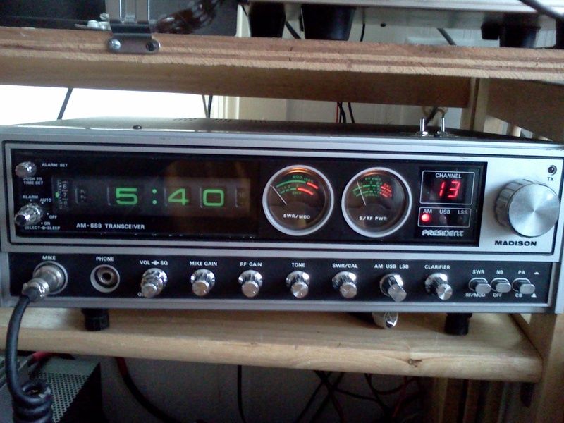 |
|
|
|
Post by MonkeyMan on Jun 6, 2017 16:06:59 GMT -5
One of my favorites. Nice find!
|
|
Sandbagger
Administrator/The Boss 
Posts: 6,250 
|
Post by Sandbagger on Jun 6, 2017 21:12:18 GMT -5
Found a new "toy" to play with while I'm waiting on a power supply donor for my Cobra 2000..Bought this at an estate sale over the week-end for 30 dollars. The lady at the sale told me it "works". It was a bit dirty, covered with oily dust (did someone forget to clean the Deer tick ointment off their fingers?) and the inside was full of dog hair, (they had some kind of a lapdog). I plugged it in and prayed ..no pops, flashes or booms. So off came the covers, top and bottom, and I filled the shop vac with a bushel of hair and debris of various origins then settled into updating the insulators on all the transistors to mica, checking board voltages etc...changing the power supply cap to a 50 volt 3300 pf from the old 25 v unit..I hear those were prone to failure a lot of the time. Checked the alignment...it was spot-on and so were the bias voltage settings..gave it a light tune-up, a major clean-up and put it on the air...I'm not so sure this radio had much talk-time before it was put on the shelf...it cleaned up nicely and looks like a new rig...the clock is dead, of course, but I have a nice frequency counter that will occupy the clock "window" here in the very near future..now I have what was needed..an 858 base radio to go with my trc-449..Like Sparky always says...it's a great thing we're doing...keeping these beautiful radios from the evil "Shredder" Ah the older brother to my Washington. Nice! I just got done HiFi'ing mine. But they talk well enough in the stock configuration. Back in the day this was my favorite chassis, because I could get more channels out of this chassis than any other, in the days before "export" radios came along. |
|
|
|
Post by "Doc"Hammer on Jun 9, 2017 0:40:45 GMT -5
Disassembled the Madison tonight to remove the dead clock assembly. That is a process not for the weak of heart! However the resulting space is perfect for my freq counter installation. A year ago, I bought a nice KEMTRON counter for the bench, thus retiring my old Land-matic unit...it's been sitting in a drawer doing nothing so I decided I'll put it in the Madison where the old clock was...Looks like it will be a good fit and when I get done, the install will be sanitary and clean...more as I work on getting it mounted..    The counter will only read on transmit, but thats ok.. |
|
Sandbagger
Administrator/The Boss
Posts: 6,250
|
Post by Sandbagger on Jun 9, 2017 6:48:44 GMT -5
Disassembled the Madison tonight to remove the dead clock assembly. That is a process not for the weak of heart! However the resulting space is perfect for my freq counter installation. A year ago, I bought a nice KEMTRON counter for the bench, thus retiring my old Land-matic unit...it's been sitting in a drawer doing nothing so I decided I'll put it in the Madison where the old clock was...Looks like it will be a good fit and when I get done, the install will be sanitary and clean...more as I work on getting it mounted.. The counter will only read on transmit, but thats ok.. So that counter lacks the offsets that allow you to run it on receive? Shame, it would be like a custom made Cobra 2000, but with the 858 board. |
|
|
|
Post by "Doc"Hammer on Jun 9, 2017 8:17:05 GMT -5
I would invest in a Galaxy FC-390, (That reads receive & transmit) and manually wire it in, but the "toy" budget is shot for this month. But that is an idea not out of the question for the future  Meanwhile, this will get the "job" done until I purchase an FC-390.. |
|
|
|
Post by bluemax on Jun 10, 2017 11:04:18 GMT -5
Found a new "toy" to play with while I'm waiting on a power supply donor for my Cobra 2000..Bought this at an estate sale over the week-end for 30 dollars. The lady at the sale told me it "works". It was a bit dirty, covered with oily dust (did someone forget to clean the Deer tick ointment off their fingers?) and the inside was full of dog hair, (they had some kind of a lapdog). I plugged it in and prayed ..no pops, flashes or booms. So off came the covers, top and bottom, and I filled the shop vac with a bushel of hair and debris of various origins then settled into updating the insulators on all the transistors to mica, checking board voltages etc...changing the power supply cap to a 50 volt 3300 pf from the old 25 v unit..I hear those were prone to failure a lot of the time. Checked the alignment...it was spot-on and so were the bias voltage settings..gave it a light tune-up, a major clean-up and put it on the air...I'm not so sure this radio had much talk-time before it was put on the shelf...it cleaned up nicely and looks like a new rig...the clock is dead, of course, but I have a nice frequency counter that will occupy the clock "window" here in the very near future..now I have what was needed..an 858 base radio to go with my trc-449..Like Sparky always says...it's a great thing we're doing...keeping these beautiful radios from the evil "Shredder" I never really paid attention to the similarities, but I see almost the same features as my Robyn SB520D. And I realized recently I have the 858 chassis also. I never liked the clock idea, but I wouldn't have argued with a headphone jack. My meters are both doa, and finding them will undoubtedly be difficult. I'm going to remove them and attempt cleaning them behind the ears; the paint from the needle is probably fouling them. But if these meters are of the same basic specs (and I would expect the meter itself isn't round) maybe there are more possible places to look for them. The Robyn S/RF meter was 520031. Does that in any way resemble the President's? My AC power supply is also dead, although not as important to me, but I would imagine many of the supplies for the same chassis could be implanted. And as long as we're talking about the 858, I apparently inherited some extra channels. I have no idea which frequencies or how many. I suppose it's time for a frequency counter other than the one in the Ranger, so I might be able to improve your budget for a new unit by keeping yours from the shredder. |
|
|
|
Post by "Doc"Hammer on Jun 10, 2017 12:02:35 GMT -5
I know the Robyn SB520 quite well...they are a nice looking rig...I just re-habbed one awhile back for a local here... Barkett Electronics has replacement meters for them: stores.goldeneagleradios.com/replacement-meter-teaberry-stalker-realistic-robyn-ect/They run as good on 12v from a power supply as they do from the built-in supply so you can bide your time on fixing the ac supply until a "Donor rig" shows up. Your meters might be dust fouled and not bad..there is a slick video on You-tube that I watched & learned how to clean and adjust meters. So far, it has worked on just about every one I tried.. www.youtube.com/watch?v=qygecXhZTxk&t=636s you will be amazed how easy it is.. |
|
|
|
Post by bluemax on Jun 10, 2017 12:58:23 GMT -5
Hey, Doc, two great tips...thanks. I figure I don't have anything to lose trying the meter tune up, and if I goof I'll buy just one. I don't use the SWR function on any radios, just the external meter.
And let me know if you want to recycle that counter sometime. Or anyone else that has one to re-purpose!
|
|
|
|
Post by BBB on Jun 11, 2017 10:28:13 GMT -5
Note on the meter repairs: the factories used a bit of thread-locker on those tiny brass needle movement screws. A small dab of Acetone (finger nail polish remover) will loosen them up so your micro screwdriver can turn 'em.
|
|
|
|
Post by "Doc"Hammer on Jun 11, 2017 11:08:39 GMT -5
Note on the meter repairs: the factories used a bit of thread-locker on those tiny brass needle movement screws. A small dab of Acetone (finger nail polish remover) will loosen them up so your micro screwdriver can turn 'em. My wife's bottle of nail polish remover came up missing awhile back...I don't know a thing about it!   |
|
|
|
Post by bluemax on Jun 13, 2017 14:18:49 GMT -5
Well I worked the meters over...worth a try. Two meters out, the S/RF won't bottom out at 0 no matter what. The SWR meter loosened up OK. Switched the scale plates and put 'em back, didn't bother connecting the now defunct SWR side, just the signal meter. Still only moves 2-3 needle widths. But a good exercise anyway. Boy, the one screw head was COVERED with measurable glue; took 4 or 5 wettings to get it free. I can see how easy it would be to chew one apart if you just went at it dry. So I'll get one good new meter and hope the glue I used isn't TOO good. Should have thought about a dry run. I can see that being over-zealous in the repair business will cost me plenty of time. Need to think the whole thing through before moving ahead.
|
|
|
|
Post by "Doc"Hammer on Jun 14, 2017 11:34:07 GMT -5
Found out the reason I slid that old Landmatic counter to the side in the first place....it was shot..So into the can it goes. I buttoned up the Madison for the time being with a plastic cover over the clock hole. Next month we invest in a Galaxy counter that reads receive and transmit. Meanwhile I'm off to study up on unlocking the clarifier on an 858 chassis. Never done one on this chassis so it will be a learning experience..if it's as easy as the 8719 board, it will be a breeze! Ironically, I got a call yesterday from a friend in Fredonia Kansas about cleaning up his 148GTL, unlocking his clarifier and wiring some mics for it...He offered me a working Robyn SB520D for doing the work along with a tasty meal at one of my favorite local eateries there in Fredonia. So tomorrow, I'm off on a roadtrip to Southeast Kansas for some fishing and to pick up more "goodies" to play with.  |
|
Sandbagger
Administrator/The Boss
Posts: 6,250
|
Post by Sandbagger on Jun 14, 2017 18:52:26 GMT -5
Found out the reason I slid that old Landmatic counter to the side in the first place....it was shot..So into the can it goes. I buttoned up the Madison for the time being with a plastic cover over the clock hole. Next month we invest in a Galaxy counter that reads receive and transmit. Meanwhile I'm off to study up on unlocking the clarifier on an 858 chassis. Never done one on this chassis so it will be a learning experience..if it's as easy as the 8719 board, it will be a breeze! Ironically, I got a call yesterday from a friend in Fredonia Kansas about cleaning up his 148GTL, unlocking his clarifier and wiring some mics for it...He offered me a working Robyn SB520D for doing the work along with a tasty meal at one of my favorite local eateries there in Fredonia. So tomorrow, I'm off on a roadtrip to Southeast Kansas for some fishing and to pick up more "goodies" to play with. The clarifier mod on the 858 chassis is just as simple as most other rigs, It's just a matter of lifting the diode that leads to the transmit frequency pot, and then moving the receive only voltage from the clarifier pot, to a voltage that is on both TX and RX. That chassis has an extra zener to drop the clarifier voltage to 6V for additional stability, and unless you're looking to make the thing slide a half channel or more, I'd leave that zener alone. |
|
|
|
Post by 2600 on Jun 15, 2017 16:30:08 GMT -5
There is one more "Gotcha" to reading frequency full-time on this radio.
The PLL shifts frequency between receive and transmit in AM mode. If memory serves, it's a 2.5 kHz jump when you key the mike. You could set your display to read correctly for one, or the other, but not for both transmit and receive.
Doesn't have this bad habit in sideband modes, only AM.
One reason you don't see a lot of displays made for this chassis. Ralph, the "fasttrack*09" guy on Ebay has one, but he used a sneaky trick to get around it. Drawback to his method is that it won't show any change when the clarifier is turned. He gets around the problem by reading the frequency that feeds into the PLL chip itself, and not the frequency that feeds into the receiver and transmit mixers like the FC390, PDC256 and such. Ralph's display translates the 910 to 1350 kHz feeding into the 858 chip to the channel frequency. It's a clever trick I wish I had thought of. But don't expect it to show you how far off channel the clarifier has slid.
Pretty sure I posted the clarifier mod or this one. One diode comes out, and a resistor gets moved from where it is on top, soldered across two pads on the solder side. Keeps that clarifier-circuit zener where it belongs. I'll try to track it down.
73
|
|
|
|
Post by 2600 on Jun 15, 2017 16:49:52 GMT -5
|
|
|
|
Post by "Doc"Hammer on Jun 16, 2017 20:53:25 GMT -5
Thanks for the link, 2600...that will be an easy mod for sure..I'll let you know how it works out.
|
|
|
|
Post by "Doc"Hammer on Jun 17, 2017 12:03:14 GMT -5
Thanks 2600 and Sandbagger...the operation was a success...Makes operation on sideband a LOT more pleasant! It slides from 27.3841 to 27.3865 on Lower 38. Plenty of slide for the DXing I do...
|
|
Sandbagger
Administrator/The Boss
Posts: 6,250
|
Post by Sandbagger on Jun 17, 2017 19:19:55 GMT -5
Thanks 2600 and Sandbagger...the operation was a success...Makes operation on sideband a LOT more pleasant! It slides from 27.3841 to 27.3865 on Lower 38. Plenty of slide for the DXing I do... That's pretty much the "standard" range for most CB radio clarifiers. If, at some point in the future, you feel that you need a bit more range, that can be accomplished fairly easy as well. +/- 5 Khz can be had with not a lot of trouble, but it may reduce stability a bit. You can also align the trimmer caps on the mixer crystals to equalize your range, or if your "center slot" does not line up at 12 O'clock. |
|
|
|
Post by 2600 on Jun 17, 2017 23:45:21 GMT -5
Ah, "stretching" the range of the clarifier on that radio is a bit trickier than on later-design radios. The three crystals must each be made to travel farther. Getting the center of the channel adjusted to 12 o'clock for all three modes can become a hair-puller.
Much simpler to do with radios that have only one PLL loop crystal. The three separate 11.28xx MHz crystals in this radio each has its own separate oscillator circuit. Gotta stretch each one separately.
73
|
|
|
|
Post by "Doc"Hammer on Jun 18, 2017 3:56:37 GMT -5
"Center slot" turned out to be 11:00 o'clock on the knob..close enough for me. The old saying "If it works, I ain't fixing it" applies here..Found "fasttrack*09" on Ebay..he's got a counter at a good price ($49) with larger digits that will fill the clock hole and a red readout..Simple 4 wire hook-up. One of the wires will go to a Test point...not sure which one, but I think I can figure it out. Will order that on Thursday. This rig is coming along nicely.  |
|
Sandbagger
Administrator/The Boss
Posts: 6,250
|
Post by Sandbagger on Jun 18, 2017 11:18:44 GMT -5
Ah, "stretching" the range of the clarifier on that radio is a bit trickier than on later-design radios. The three crystals must each be made to travel farther. Getting the center of the channel adjusted to 12 o'clock for all three modes can become a hair-puller. Much simpler to do with radios that have only one PLL loop crystal. The three separate 11.28xx MHz crystals in this radio each has its own separate oscillator circuit. Gotta stretch each one separately. 73 Depends on how much you want to "stretch" it. Simply jumping out R116 and lifting D32 will give you close to +/- 5 Khz. No guarantee that each mode will track exactly, but it shouldn't be any worse than the older Toshiba chassis radios that shift mode offset by moving clarifier voltage ranges. With PLL radios like this, it's pretty much senseless to increase clarifier range beyond +/- 5 Khz anyway since you can fill in any 10 Khz "hole" with the PLL programming. The 858 will actually do 5 Khz steps as well, but that is a mess to track with just the selector and added switches. That's a job best left to an external programmer. |
|


 ..no pops, flashes or booms. So off came the covers, top and bottom, and I filled the shop vac with a bushel of hair and debris of various origins then settled into updating the insulators on all the transistors to mica, checking board voltages etc...changing the power supply cap to a 50 volt 3300 pf from the old 25 v unit..I hear those were prone to failure a lot of the time. Checked the alignment...it was spot-on and so were the bias voltage settings..gave it a light tune-up, a major clean-up and put it on the air...I'm not so sure this radio had much talk-time before it was put on the shelf...it cleaned up nicely and looks like a new rig...the clock is dead, of course, but I have a nice frequency counter that will occupy the clock "window" here in the very near future..now I have what was needed..an 858 base radio to go with my trc-449..Like Sparky always says...it's a great thing we're doing...keeping these beautiful radios from the evil "Shredder"


 Meanwhile, this will get the "job" done until I purchase an FC-390..


